De-interlacing method and apparatus

a technology of interlacing method and interlacing apparatus, which is applied in the direction of picture reproducers using projection devices, signal generators with optical-mechanical scanning, television systems, etc., can solve the problems of unsatisfactory edge base line average methods, and achieve the enhancement of the correctness of each of the interpolated luminance value and the interpolated chrominance value, so as to reduce the need for calculation and improve the accuracy of each interpolated luminance value and interpolated chrominance valu

Inactive Publication Date: 2008-03-27
HIMAX TECH LTD
View PDF6 Cites 13 Cited by
  • Summary
  • Abstract
  • Description
  • Claims
  • Application Information

AI Technical Summary

Benefits of technology

[0008]The invention is directed to a de-interlacing method and a de-interlacing apparatus. An edge-direction value of a to-be-interpolated pixel is calculated according to edge-direction values of specific display pixels near the to-be-interpolated pixel, and a corresponding display pixel pair is selected in the display lines above and under the to-be-interpolated pixel according to a corresponding edge direction so that a luminance value and a chrominance value can be obtained by way of interpolation. Thus, the required calculation can be reduced, and the correctness of each of the interpolated luminance value and the interpolated chrominance value can be greatly enhanced.

Problems solved by technology

However, this edge base line average method is not perfect because determining the best edge direction according to the luminance difference of the corresponding pixel pair may have errors.

Method used


Image

  • De-interlacing method and apparatus
  • De-interlacing method and apparatus
  • De-interlacing method and apparatus

Examples


Embodiment Construction

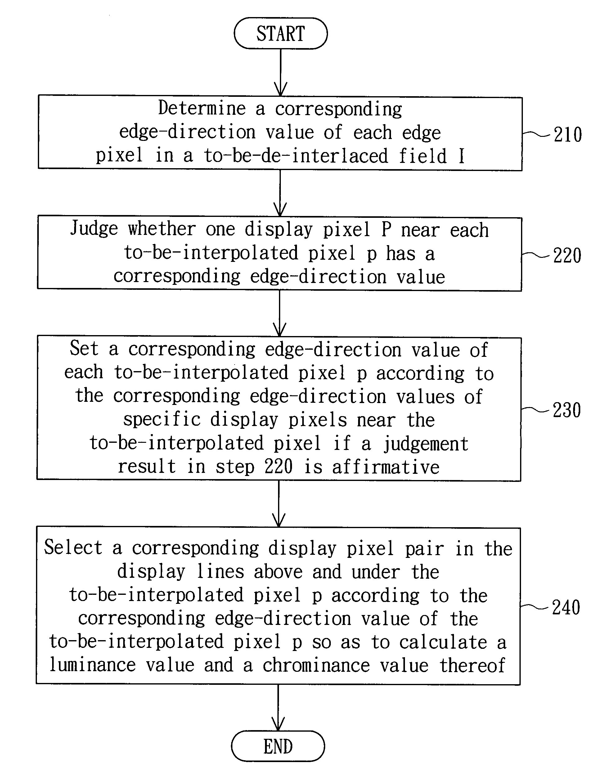
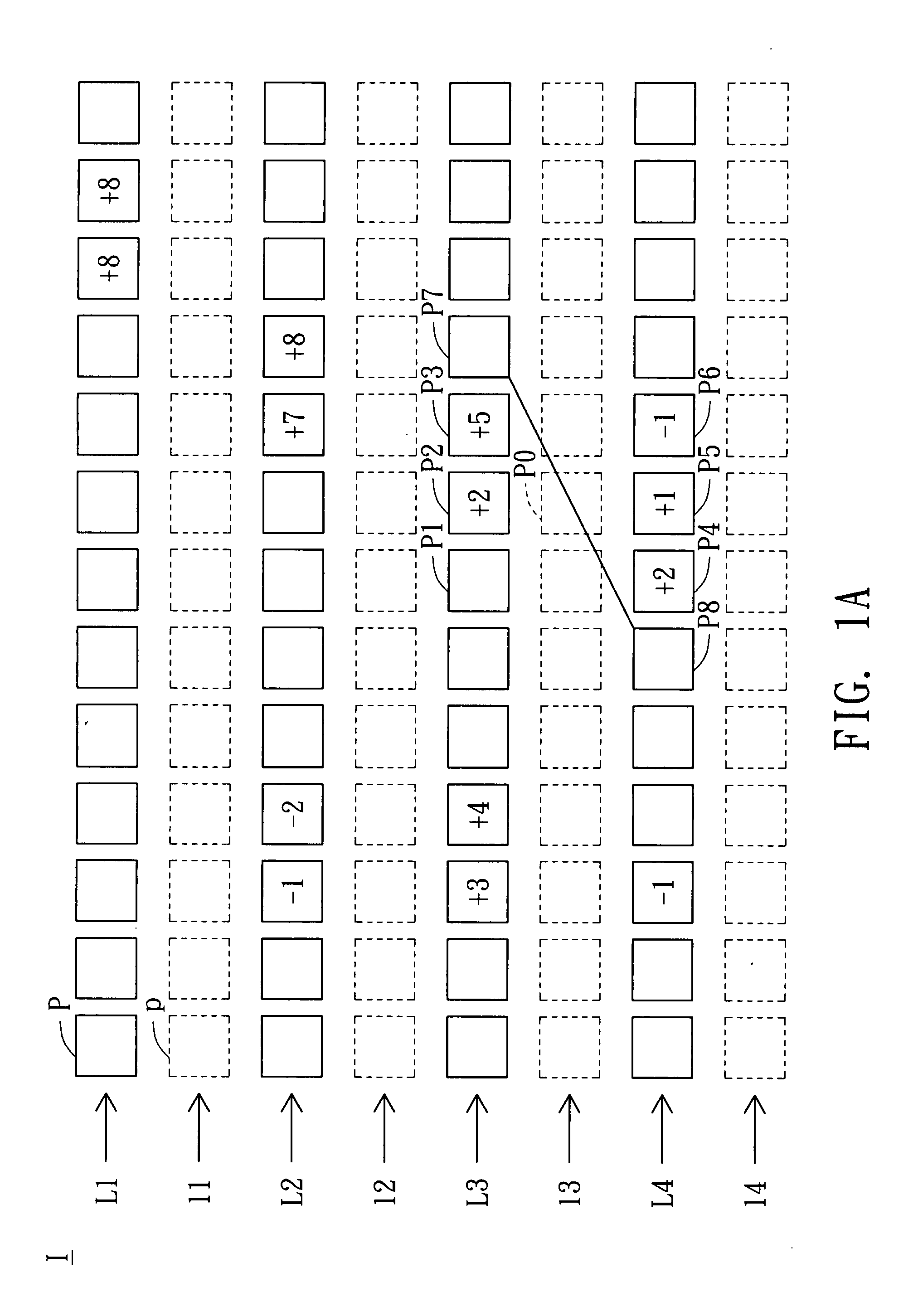
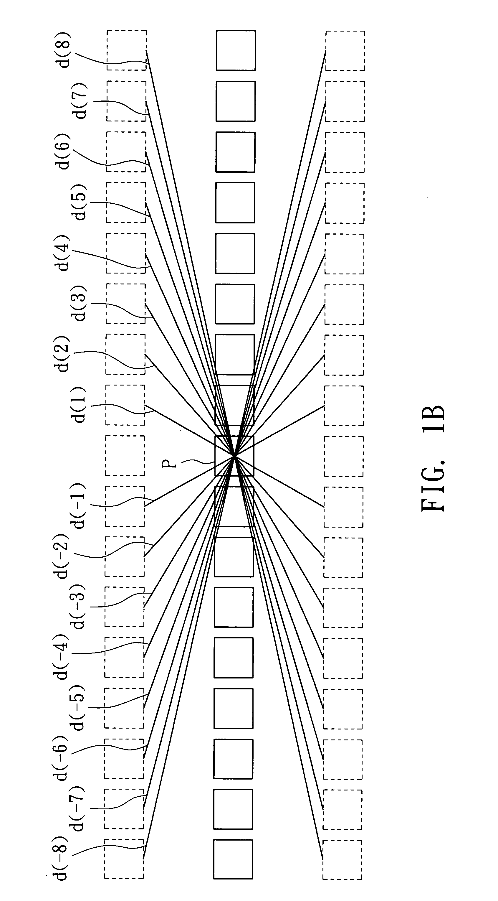
[0016]FIG. 1A is a partial schematic illustration showing a to-be-de-interlaced field I according to a preferred embodiment of the invention. FIG. 1B is a schematic illustration showing an edge direction d(i) corresponding to each edge-direction value i. The to-be-de-interlaced field I, such as the odd field, includes several display lines L1 to L4 and several to-be-interpolated lines I1 to I4. Each display pixel P of each display line is represented by a solid-line frame. Each to-be-interpolated pixel p of each to-be-interpolated line is represented by a dashed-line frame. In addition, some display pixels P have edge-direction values, such as the values labeled in the solid-line frame of FIG. 1A.

[0017]In the preferred embodiment of the invention, the edge-direction value may be obtained by using various edge detection algorithms, such as the Sobel, Canny or Prewitt type edge detection algorithm, to obtain the edge pixel of the to-be-de-interlaced field I and then further analyzing ...


PUM


Abstract

A de-interlacing method is applied to a to-be-de-interlaced field including display pixels of display lines and to-be-interpolated pixels of to-be-interpolated lines. First, a corresponding edge-direction value of each of edge pixels in the to-be-de-interlaced field is determined. Next, it is judged whether one of the display pixels near each to-be-interpolated pixel has a corresponding edge-direction value so that a judgement result is obtained. Then, a corresponding edge-direction value of each to-be-interpolated pixel is set according to the corresponding edge-direction values of specific display pixels of the display pixels near the to-be-interpolated pixel if the judgement result is affirmative. Finally, a corresponding display pixel pair of up and down display lines near each to-be-interpolated pixel is selected according to the corresponding edge-direction value of each to-be-interpolated pixel so that a luminance value and a chrominance value of the to-be-interpolated pixel are calculated.

Description

[0001]This application claims the benefit of Taiwan application Serial No. 95135617, filed Sep. 26, 2006, the subject matter of which is incorporated herein by reference.BACKGROUND OF THE INVENTION[0002]1. Field of the Invention[0003]The invention relates in general to a de-interlacing method and a de-interlacing apparatus, and more particularly to a de-interlacing method and a de-interlacing apparatus using a direction map.[0004]2. Description of the Related Art[0005]The typical video is played in an interlaced manner. When each frame is being displayed, an odd field is first displayed, and then an even field is displayed. The odd field is composed of odd display lines of the frame, while the even field is composed of even display lines of the frame.[0006]However, the more advanced image playing device, such as a high definition television (HDTV), supports the non-interlaced display. Thus, a de-interlacing method is required to de-interlace the fields, which are displayed in the in...

Claims


Application Information

Patent Timeline
Patent Type & Authority Applications(United States)
IPC IPC(8): H04N7/01
CPCH04N7/0142H04N7/012
Inventor CHANG, FANG-CHEN
Owner HIMAX TECH LTD
Why Eureka
Try Eureka