Separable sorption apparatus

a sorption apparatus and a technology of a sorption apparatus, which are applied in the direction of dispersed particle separation, separation processes, disinfection, etc., can solve the problems of limited sorption efficiency of the conventional sorption apparatus, inability to improve, and high cost of each conventional sorption apparatus, so as to improve the sorption effect and the effect of ample internal spa

Inactive Publication Date: 2015-02-17
HSU TSANG HUNG
View PDF7 Cites 0 Cited by
  • Summary
  • Abstract
  • Description
  • Claims
  • Application Information

AI Technical Summary

Benefits of technology

[0011]The sorption device is put in a room that needs dehumidifying or deodorizing. When the sorbent granules have become saturated, the heater of the heating device is mounted into the sorption device to dehumidify or deodorize the sorption device to allow the sorption device to be reused. Since the heating device is detachable, the heating device does not occupy internal space of the sorption device. Thus, the sorption device has ample internal space for receiving the sorbent granules. Consequently, the sorption device has improved sorption effect.

Problems solved by technology

In enclosed places, such as bathrooms, closets, storage rooms and the like, of a house, mold and mildew grow easily so causing goods stored in the enclosed places being damped, damaged and rotten.
However, the heating device that is securely assembled in the housing of the conventional sorption apparatus and undetachably occupies internal space of the conventional sorption apparatus and the internal space would be more efficiently used if the internal space were to contain more of the sorption agent.
Therefore, the sorption efficiency of the conventional sorption apparatus is limited and is unable to be improved.
Moreover, since the heating device comprises numerous components such as a heater, a heat sink, multiple insulation sheets, multiple wires and so on, and each conventional sorption apparatus has a heating device, cost of each conventional sorption apparatus is bound to be high.
Furthermore, as long as the heating device has the numerous components, the conventional sorption apparatus has complicated assembling processes and breaks down easily.

Method used


Image

  • Separable sorption apparatus
  • Separable sorption apparatus
  • Separable sorption apparatus

Examples


Embodiment Construction

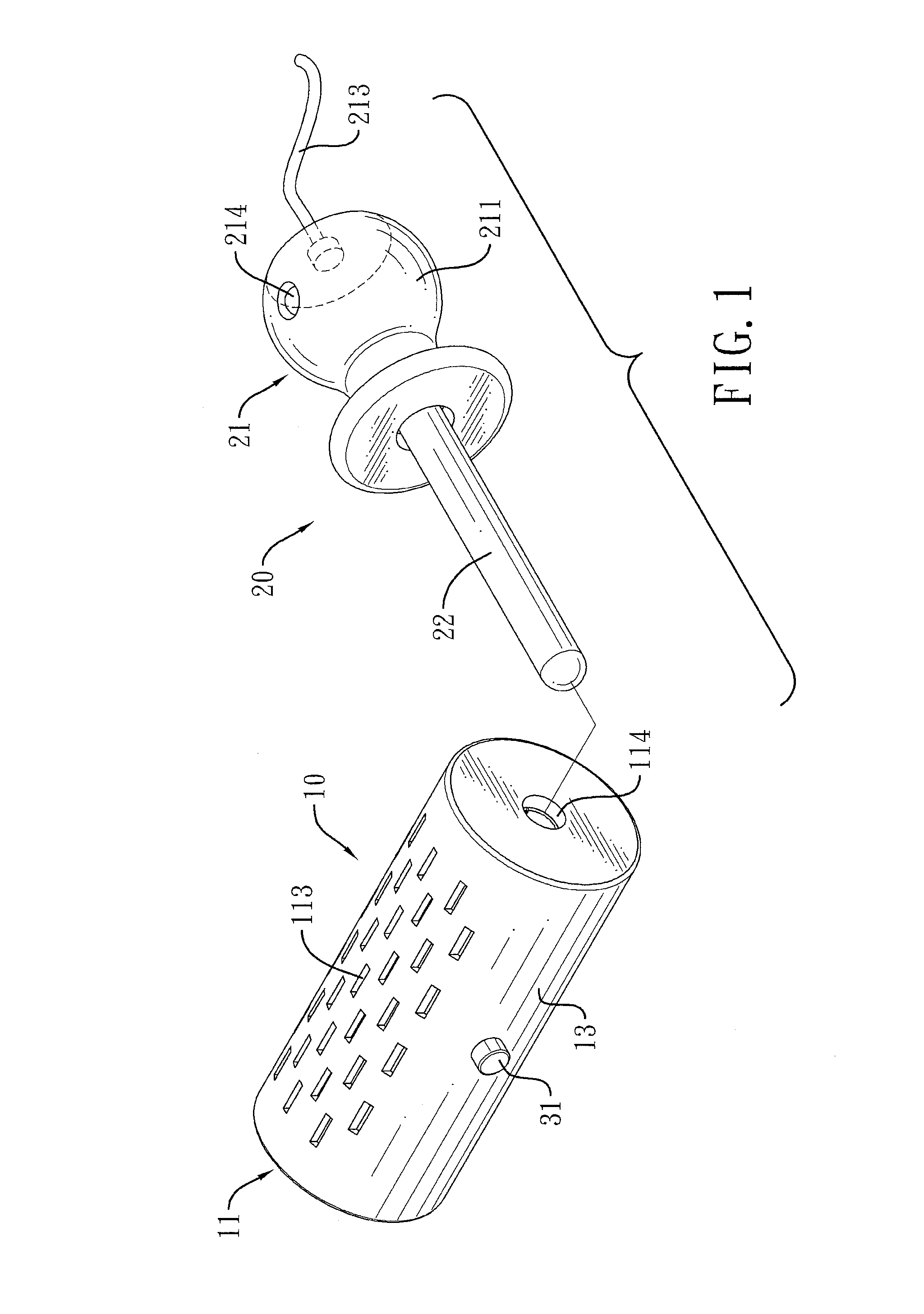
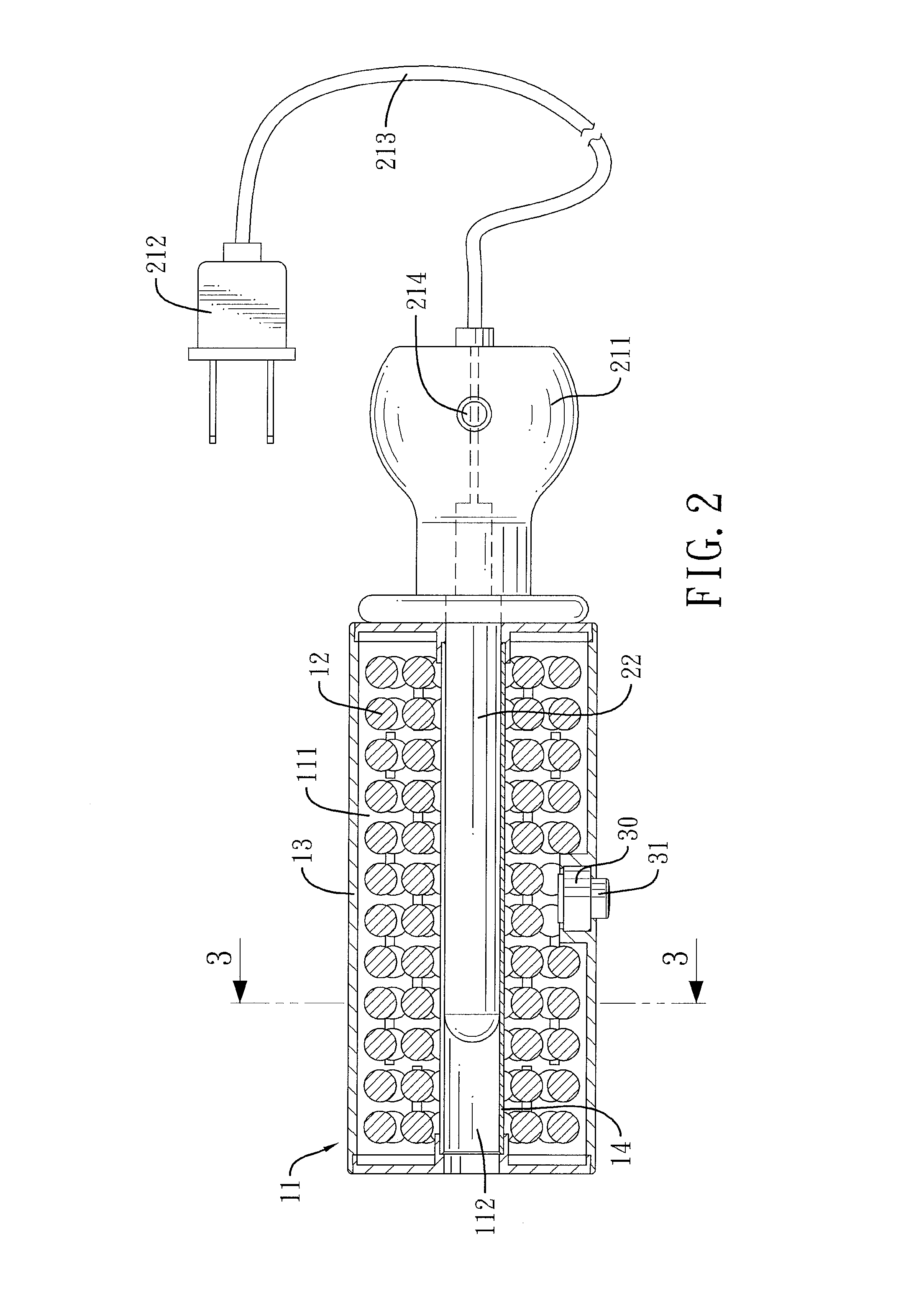
[0021]With reference to FIG. 1, a separable sorption apparatus in accordance with the present invention comprises a sorption device 10 and a heating device 20.

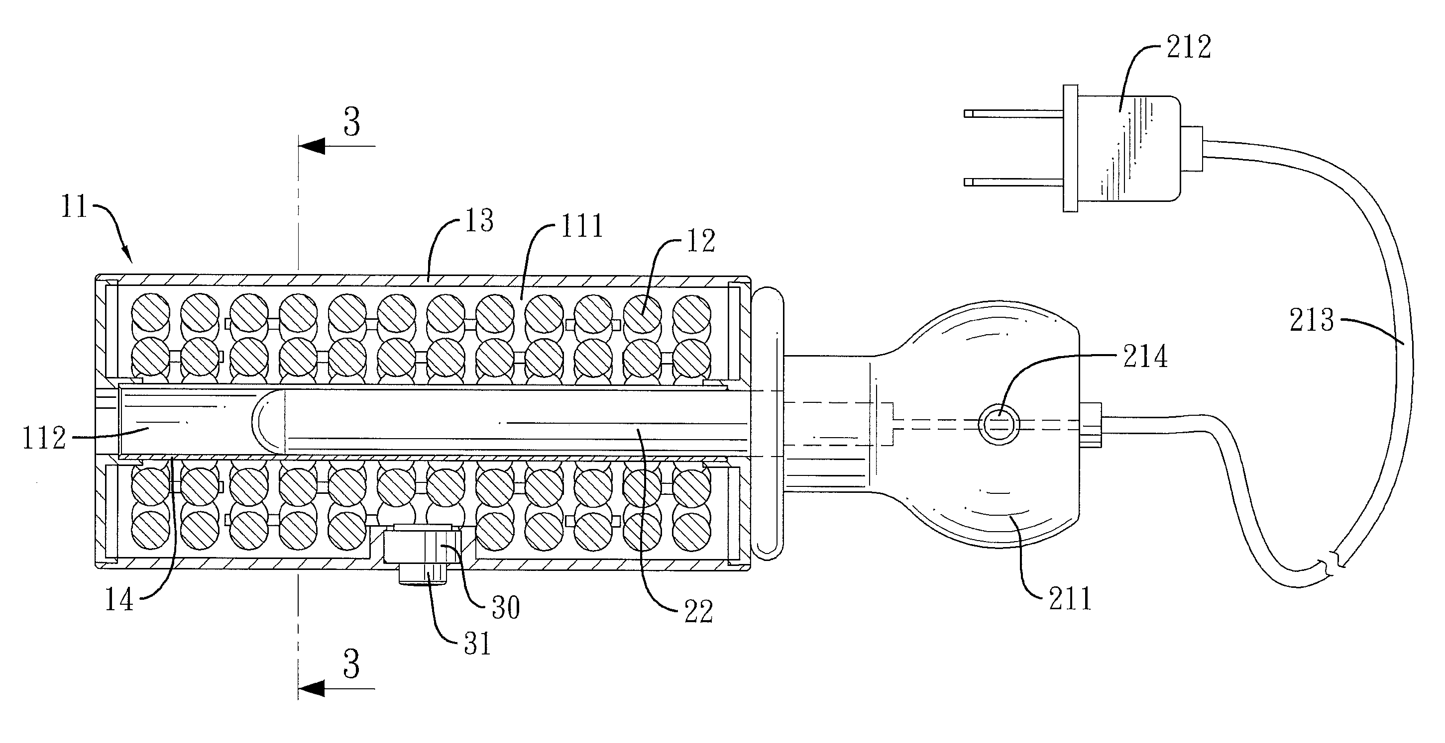
[0022]With further reference to FIG. 2, the sorption device 10 has a housing 11, multiple sorbent granules 12 and a sensor 30.

[0023]The housing 11 has an outer sidewall, a first chamber 111, a second chamber 112, multiple ventilation holes 113 and at least one opening 114. The first chamber 111 is defined in the housing 11. The second chamber 112 is defined in the housing 11 and is separate from the first chamber 111. The ventilation holes 113 are formed through the outer wall of the housing 11 and communicate with the first chamber 111. The at least one opening 114 is formed through the outer wall of the housing 11 and communicates with the second chamber 112.

[0024]With further reference to FIGS. 3, 5, 6, 7 and 8, in the preferred embodiment of the present invention, the housing 11 has an outer casing 13 and a conducting tube...


PUM

PropertyMeasurementUnit
poweraaaaaaaaaa
relative humidityaaaaaaaaaa
resilientaaaaaaaaaa

Abstract

A separable sorption apparatus has a sorption device and a heating device. The sorption device is filled with multiple sorbent granules. The heating device is detachably mounted on the sorption device and has a heater. The sorption device is put in a room that needs dehumidifying or deodorizing. When the sorbent granules have become saturated, the heater of the heating device is mounted into the sorption device to dehumidify or deodorize the sorption device to allow the sorption device to be reused. Since the heating device is detachable, the heating device does not occupy internal space of the sorption device. Thus, the sorption device has ample internal space for receiving the sorbent granules. Consequently, the sorption device has improved sorption effect.

Description

BACKGROUND OF THE INVENTION[0001]1. Field of the Invention[0002]The present invention relates to a sorption apparatus, especially to a separable sorption apparatus.[0003]2. Description of the Prior Art(s)[0004]In enclosed places, such as bathrooms, closets, storage rooms and the like, of a house, mold and mildew grow easily so causing goods stored in the enclosed places being damped, damaged and rotten. Therefore, to control relative humidity and distinctive odors in the enclosed places is important.[0005]Conventional sorption apparatuses that are used for dehumidifying or removing the distinctive odors have been developed. A conventional sorption apparatus, as disclosed in Taiwan Utility Patent with Patent No. 431585, has a housing and a heating device. The housing is filled with a dehumidifying agent and has multiple ventilation holes formed through an outer wall of the housing. The heating device is assembled in the housing. The conventional sorption apparatus is put in a place w...

Claims


Application Information

Patent Timeline
Patent Type & Authority Patents(United States)
IPC IPC(8): B01D53/04A61L9/16B01D53/18
CPCB01D53/18B01D53/0415B01D53/0438A61L9/16B01D2253/102B01D2257/80B01D2257/90B01D2258/06B01D2259/40096B01D2259/4508A61L2209/111
Inventor HSU, TSANG-HUNG
Owner HSU TSANG HUNG
Why Eureka
Try Eureka