Uniaxially coupled double-wind driven generator

A wind-driven generator and single-axis technology, applied in the direction of wind-driven generator components, wind-driven engines, wind-driven motor combinations, etc., can solve problems such as inconvenience, large deflection force of the generator support frame, and inappropriate application of large-scale generators, etc., to achieve Easy to use, high heat dissipation efficiency, and superior performance

Inactive Publication Date: 2013-08-07
GUANGXI YINHE WIND POWER +1
View PDF5 Cites 0 Cited by
  • Summary
  • Abstract
  • Description
  • Claims
  • Application Information

AI Technical Summary

Problems solved by technology

However, due to the large rotation radius of the rotor shell, the bias force on the generator support frame is relatively large, and the existing outer rotor structure is not suitable for large generators
[0003] This shows that above-mentioned existing outer rotor wind-driven generator obviously still has inconvenience and defect in structure and use, and urgently needs to be further improved

Method used


Image

  • Uniaxially coupled double-wind driven generator
  • Uniaxially coupled double-wind driven generator
  • Uniaxially coupled double-wind driven generator

Examples


Embodiment Construction

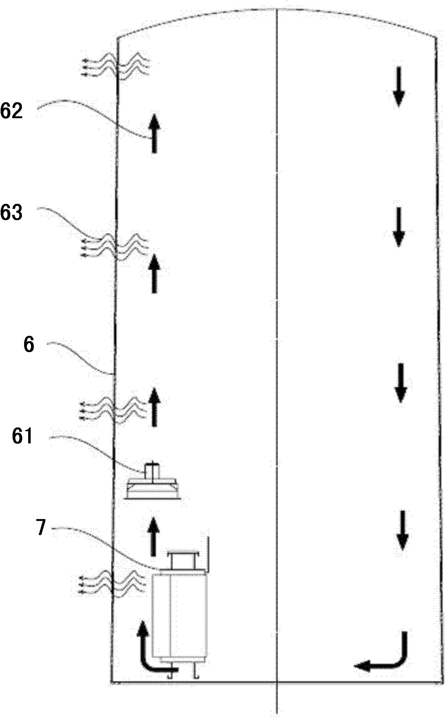
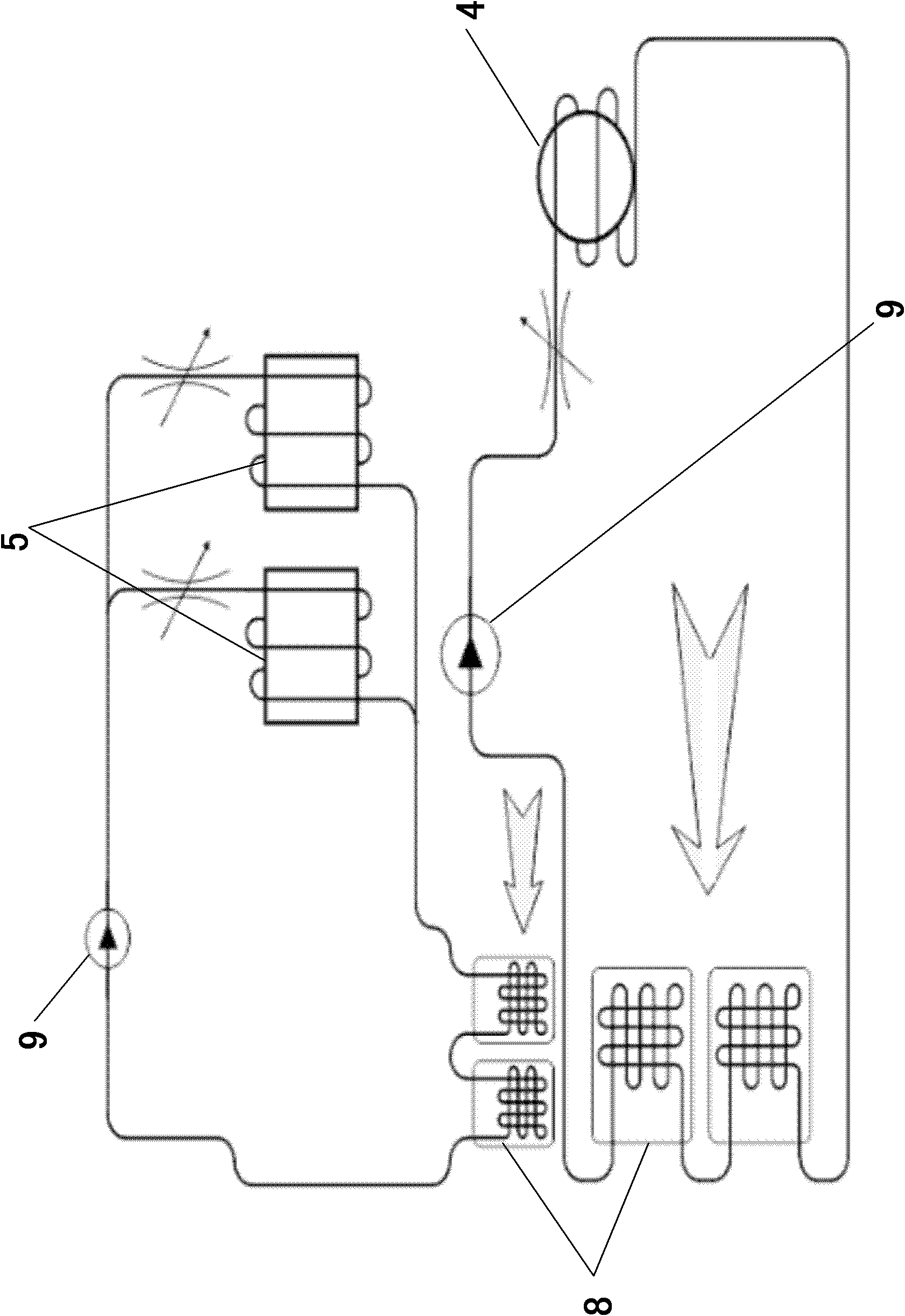
[0030] see figure 1 As shown, the single-shaft coupled dual wind power generator of the present invention mainly includes a tower 6 , a main frame 1 , a main shaft 2 , a hub 3 , a converter and two wind power generators 4 .

[0031] Among them, the two wind power generators 4 are medium voltage (MV) megawatt variable speed permanent magnet wind power generators, both of which are mainly composed of an inner stator 41 and an outer rotor 42 .

[0032] The stator 41 is preferably a coil winding made of rectangular copper conductors, forming multiple parallel circuits, using a three-phase system.

[0033] The rotor 42 is a permanent magnet, preferably a bipolar permanent magnet system. Each pole is connected by a plurality of magnetic steel blocks through clamps and interference rings. The outer surface of the magnetic steel blocks is provided with electroplating or epoxy anti-corrosion coating. A copper layer is provided between the anti-corrosion coatings of the magnetic steel ...


PUM


Abstract

A single shaft coupled double-aerogenerator comprises a tower(6),a main machine frame(1),a main shaft(2),a wheel hub(3),a current transformer(5) and two aerogenerators(4),in which the middle of the main machine frame is connected with the tower securely, the main shaft is connected with the wheel hub and fixed on the main machine frame by a main bearing(21).The two aerogenerators are mainly provided with an inner stator(41) and an outer rotor(42) and fixed on the two ends of the main machine frame by the stator. The rotors of the two aerogenerators are connected with the main shaft. The stator side of each aerogenerator is connected with one or more independent full power current transformers that is parallel connection together and connected with an electric network. The single shaft coupled double-aerogenerator adopts a structure design of an outer rotor and an inner stator so having a compact structure, adopts a design of two generators thereby being capable of balancing the carrying capability of the generator bracing frame and helpful in prolonging the service lifetime of the generator tower, and applicable to the large generator system thus overcoming the defects of the current outer rotor aerogenerator.

Description

technical field [0001] The invention relates to a generator, in particular to a single-shaft coupled double wind power generator. Background technique [0002] In recent years, wind turbines with outer rotor and inner stator have been gradually popularized and used because of their advantages of compact structure, space saving, exquisite design, and easy cooling. However, due to the large rotation radius of the rotor casing, the biasing force on the generator support frame is relatively large, and the existing outer rotor structure is not suitable for application to large generators. [0003] This shows that above-mentioned existing outer rotor wind-driven generator obviously still has inconvenience and defect in structure and use, and urgently needs to be further improved. How to create a single structure with a compact outer rotor and inner stator structure, which can balance the force of the generator support frame, which is beneficial to prolong the life of the generato...

Claims


Application Information

Patent Timeline
Patent Type & Authority Patents(China)
IPC IPC(8): H02K16/00H02K11/00H02K1/27H02K9/04
CPCY02E10/725Y02E10/722F05B2240/40F03D11/028F03D9/002F03D9/25F03D15/20Y02E10/72
Inventor 睿礼贺
Owner GUANGXI YINHE WIND POWER
Why Eureka
Try Eureka