
Floor protection device for vehicle cab

a protection device and vehicle cab technology, applied in the direction of roofs, shields, transportation and packaging, etc., can solve the problems of insufficient energy absorption capacity of the linking means, inability to use the free space located under the vehicle to house equipment or components of the vehicle itself, and insufficient device described by this patent. to achieve the effect of preventing deterioration of protection efficiency

Active Publication Date: 2015-02-24
NEXTER SYST SA
View PDF46 Cites 16 Cited by
  • Summary
  • Abstract
  • Description
  • Claims
  • Application Information

AI Technical Summary

Benefits of technology

The purpose of this invention is to create a device that offers strong protection for the floor of a vehicle with minimal amounts of material. Additionally, it allows the space underneath the floor to be utilized without compromising the protection.

Problems solved by technology

However, the device described by this patent does not provide sufficient protection for the vehicle floor.
The energy absorption capacities of the linking means are, in fact, insufficient.
Furthermore, the solutions described by DE19913845 do not enable the free space located under the vehicle to be used to house equipment or components of the vehicle itself.
The protection capacities of such a device are also insufficient.

Method used


Image

  • Floor protection device for vehicle cab
  • Floor protection device for vehicle cab
  • Floor protection device for vehicle cab

Examples


Embodiment Construction

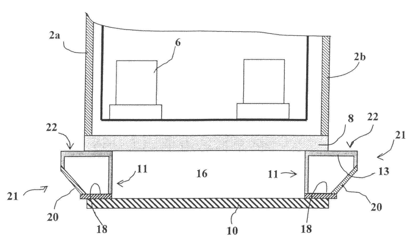
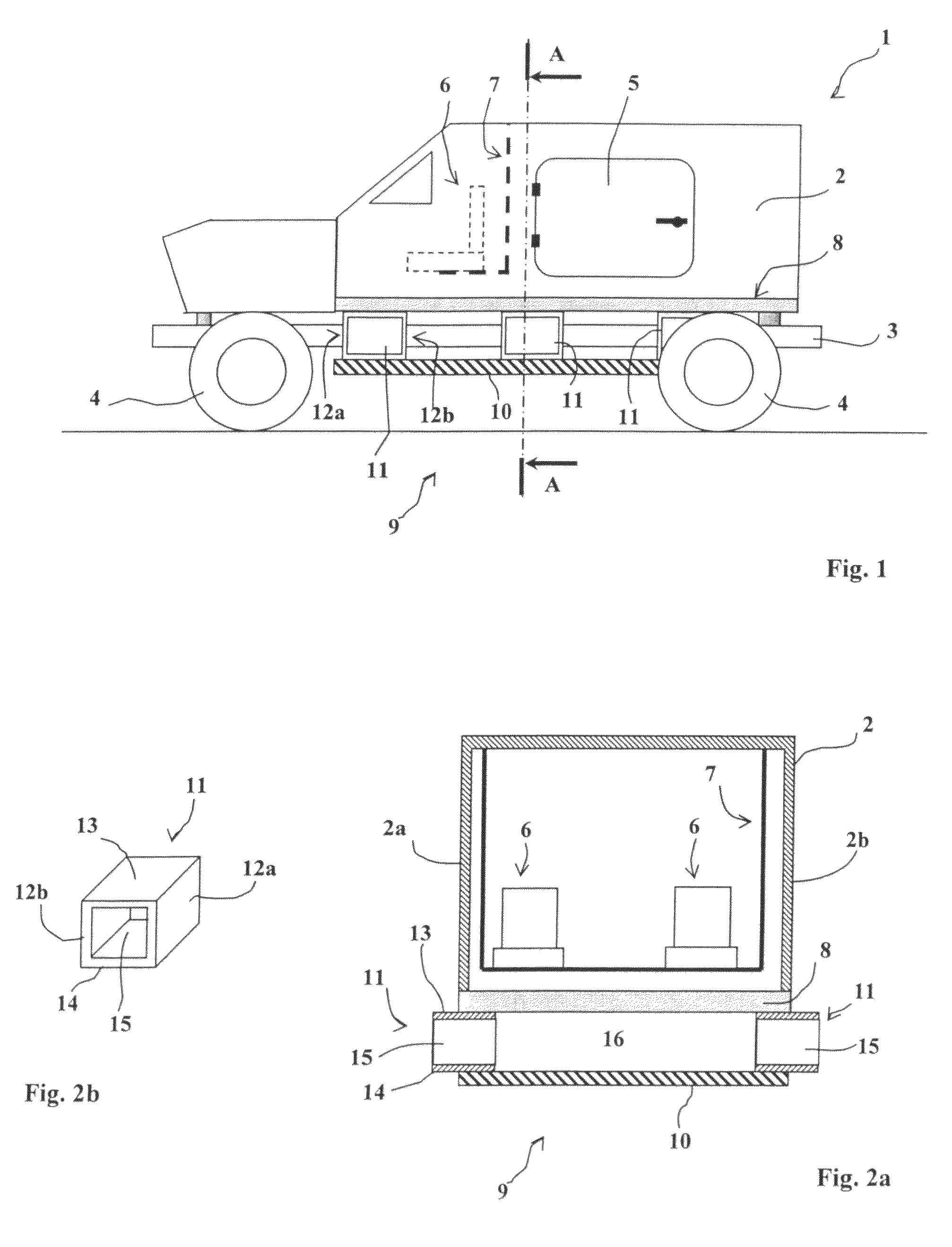
[0026]With reference to FIG. 1, a light armoured vehicle 1 comprises a cab 2 fixed to a chassis 3 equipped with wheels 4. The inside of the cab can be accessed by a door 5 and it encloses seats 6 which are suspended from the cab roof by a support frame 7. Such an arrangement is classical and enables the seats to be isolated from the cab floor 8, thereby protecting the crew from the effects on the floor further to a mine exploding.

[0027]In accordance with the invention, a floor protection device 9 is provided that comprises an armour plate 10 (for example, of steel) that is positioned at a distance from the cab floor 8.

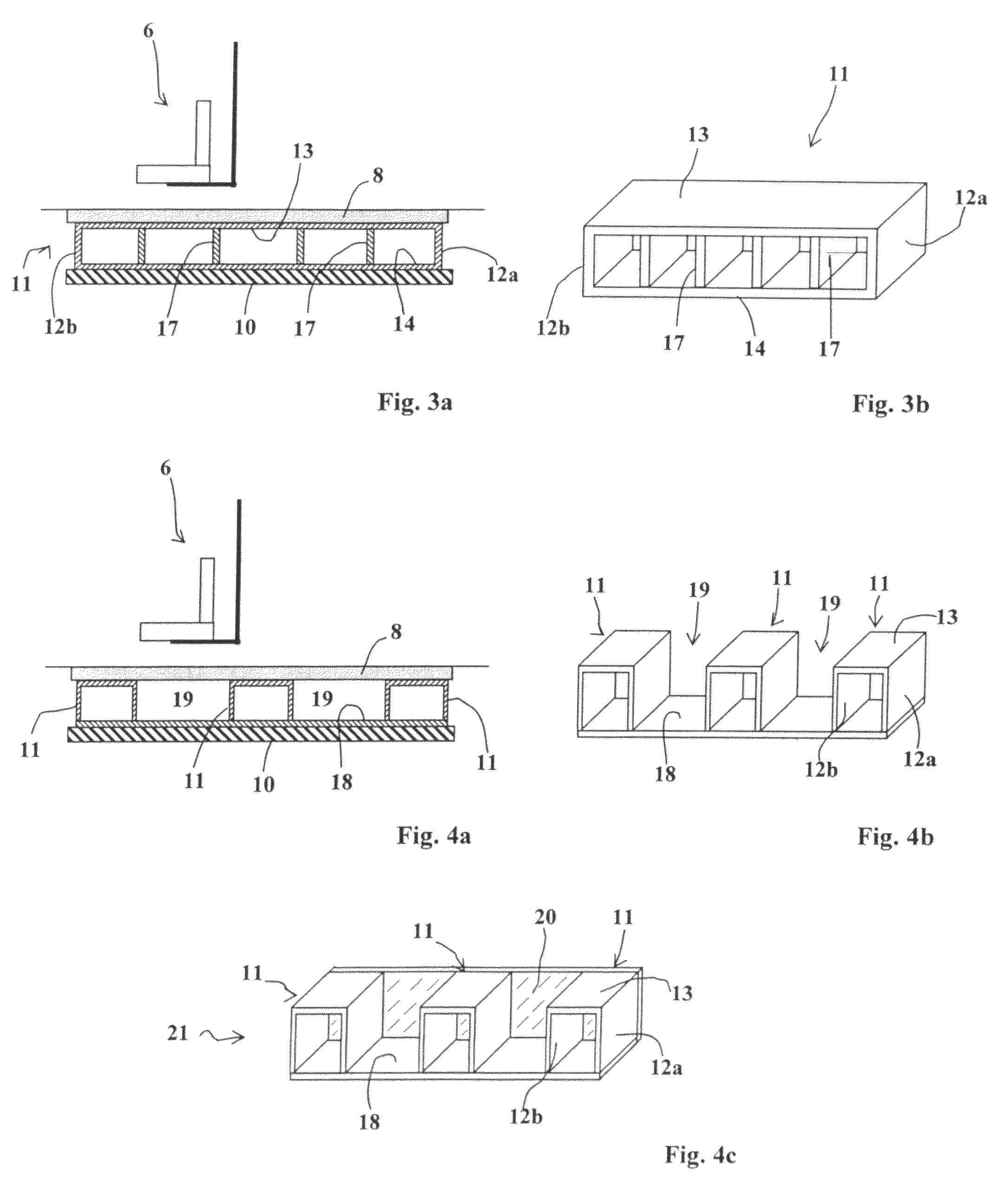
[0028]The plate 10, is fastened to the cab 2 by means of deformable linking means 11. In accordance with the invention, at least one of the deformable linking means 11 (and preferably all the linking means 11) is constituted by a compartmented caisson. FIGS. 1 and 2a show that the armour plate 10 is fastened by three caissons 11 arranged on each side of the vehicle.

[00...


PUM


Abstract

A protection device for a vehicle cab having a floor and two vertical side walls, the device including an armor plate below and substantially parallel to the floor of the cab, and deformable compartmented caissons connected between the floor and the armor plate and under the side walls of the cab, each compartmented caisson having buckleable walls dimensioned to buckle upon shock impact to the exterior of the armor plate.

Description

[0001]This application is a national state entry of International Application No. PCT / FR2009 / 000684, filed Jun. 10, 2009 designating the U.S., which claims the benefit of French Application No. 08.03278, filed Jun. 12, 2008.TECHNICAL FIELD OF THE INVENTION[0002]The technical scope of the invention is that of floor protection devices for a vehicle cab and namely the floor of a military vehicle.TECHNICAL BACKGROUND OF THE INVENTION[0003]It is known to ensure the protection of a vehicle floor by placing an armour plate at a distance from this floor, such plate being fastened to the cab by deformable linking means such as flexible mounts. Patent DE19913845 discloses such a protection device.[0004]The aim is to absorb part of the blast effect of the mine through the deformation of the armour plate whilst leaving a free space enabling the plate to deform without impacting the floor. The deformable linking means also absorb part of the energy of the shock.[0005]However, the device describe...

Claims


Application Information

Patent Timeline
Patent Type & Authority Patents(United States)
IPC IPC(8): F41H7/04
CPCF41H7/042
Inventor JACQUEMONT, JACKYNOEL, CHRISTIANPOIRMEUR, XAVIERBETTENCOURT, BENOIT
Owner NEXTER SYST SA
Learn More