
Streamer ball

a streamer ball and ball technology, applied in the field of streamers, can solve the problems of streamer ball interference, streamer ball destruction relatively quickly, bats in sets of bats and balls costing a lot of money, and the distance that the ball can travel effectively reduced

Inactive Publication Date: 2015-08-25
LIMPET SPORTS MANAGEMENT
View PDF17 Cites 4 Cited by
  • Summary
  • Abstract
  • Description
  • Claims
  • Application Information

AI Technical Summary

Benefits of technology

The patent is about a streamer ball used in sports equipment. The ball has a spacer stem and a tail which is designed to prevent the streamer from becoming tangled in the impact body and to attach the tail to the impact body. The streamer also has a cover element to protect the impact body from damage. The tail is made of a flexible plastics material that generates a pleasing noise during flight. The technical effects of the streamer ball include its durability, safety, and noise-generating performance.

Problems solved by technology

Firstly, the use of a tail which trails behind the ball in flight creates drag which slows the ball down so that when the ball is struck with a bat, the distance that the ball can travel is effectively reduced, thereby permitting a tennis-type ball game to be played in a relatively small area while the ball can still be struck at “full strength”.
A disadvantage associated with the use of a ball having a tail formed of a plurality of streamers which are directly attached to the ball as is disclosed in U.S. Pat. No. 5,813,931, is that the tail, during play, becomes tangled with the bat or the ball, resulting in interference with the flight of the streamer ball and the streamers being destroyed relatively quickly.
The cost of the bats in sets of bats and balls is the major component of such sets.
Such streamer balls having relatively lightweight impact bodies are unable to achieve the compressibility required for adequate impact performance, due to their lack of mass in relation to the compressibility of the frontal impact zone of such impact bodies.
For this reason, overhead service similar to that in tennis, is impractical as the shuttlecock is unstable at the low speeds of the shuttlecock when it is tossed up by hand prior to the service stroke.
Secondly, as badminton games are played with tensioned racquets, the base of the shuttlecock has negligible resilient compressibility as the inherent resilience and compressibility of the racquet face provides the required trampoline effect upon impact with the base of the shuttlecock.
As such, a shuttlecock is entirely unsuitable for playing a game wherein the shuttlecock is struck by a bat having an untensioned, rigid ball-striking surface.
Thirdly, the portion of the skirt of a shuttlecock which projects from the base, typically has a high mass relative to the total mass of the shuttlecock (typically approximately 30% of the total mass of the shuttlecock) which permits a tumbling net shot to be played wherein the shuttlecock is sliced at low speeds causing it to tumble over a few times. As bounce is not allowed in badminton games, the relatively high mass of the skirt is not disadvantageous but desirable so as to produce the required flight characteristics for badminton games.
Fourthly, as the skirt of the shuttlecock is directly attached to and extends directly outwardly from the base, this presents similar problems to those encountered with streamer balls wherein the streamers are directly attached to the ball, namely, that if the shuttlecock is struck at an angle to its flight path by a bat, the skirt is often struck causing damage to the skirt.
In addition, the skirt protrudes outwardly from the base at a far greater angle than the spacer stem and tails of a streamer ball which exacerbates the problem.
Fifthly, because the mass of the skirt is relatively high compared to the mass of the base and consequently as the centre of the mass of the shuttlecock is spaced a significant distance rearwardly of the centre of mass of the base (without the skirt), the shuttlecock takes a relatively long time to turn over after impact by a bat and regain an aerodynamically stable attitude in flight, thereby rendering the shuttlecock unsuitable for playing games at low speeds in relatively small playing areas.
Although the shuttlecock disclosed in U.S. Pat. No. 4,538,818 is designed to bounce it still suffers from the same deficiencies as described hereinabove in relation to a conventional shuttlecock.
In addition, as the mass of the skirt is relatively high compared to the mass of the base, causing the centre of mass of the shuttlecock to be spaced a significant distance rearwardly of the centre of mass of the base (without the skirt), the shuttlecock takes a relatively long time to turn over in flight and also to regain an aerodynamically stable attitude in flight, thereby rendering the shuttlecock unsuitable for playing games in relatively small playing areas.
Furthermore, the offset between the centre of mass of the shuttlecock and the centre of mass of the base (without the skirt) causes erratic bounce off a playing surface due to the centre of mass of the shuttlecock being spaced a significant distance rearwardly of the impact zone of the base.
The shuttlecock design disclosed in U.S. Pat. No. 4,538,818 cannot be applied to shuttlecocks having relatively small bases (of a size smaller than that of a tennis ball) as either the lack of mass in the smaller base will render it unstable in flight and unable to compress sufficiently at impact or if the density of the base is increased it renders the base less resilient and unable to achieve the compressibility required for adequate impact performance.

Method used


Image

  • Streamer ball
  • Streamer ball
  • Streamer ball

Examples


second embodiment

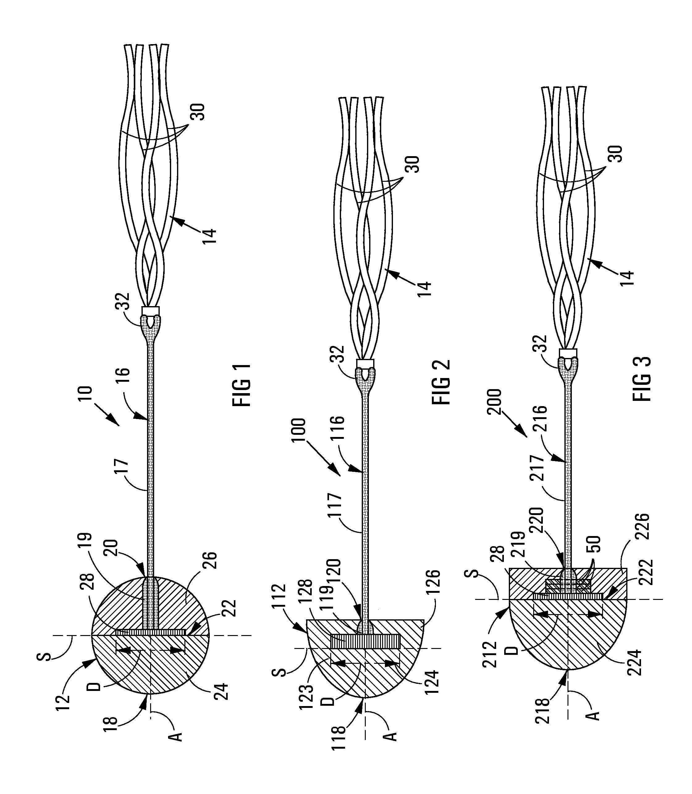
[0053]With reference to FIG. 2 of the drawings, a streamer ball in accordance with the invention is designated generally by the reference numeral 100. The streamer ball 100 is similar to the streamer ball 10, with a difference being the configuration of the impact body. As such, in FIG. 2, those features of the streamer ball 100 which are the same as and / or similar to those of the streamer ball 10 are designated by the same and / or similar reference numerals.

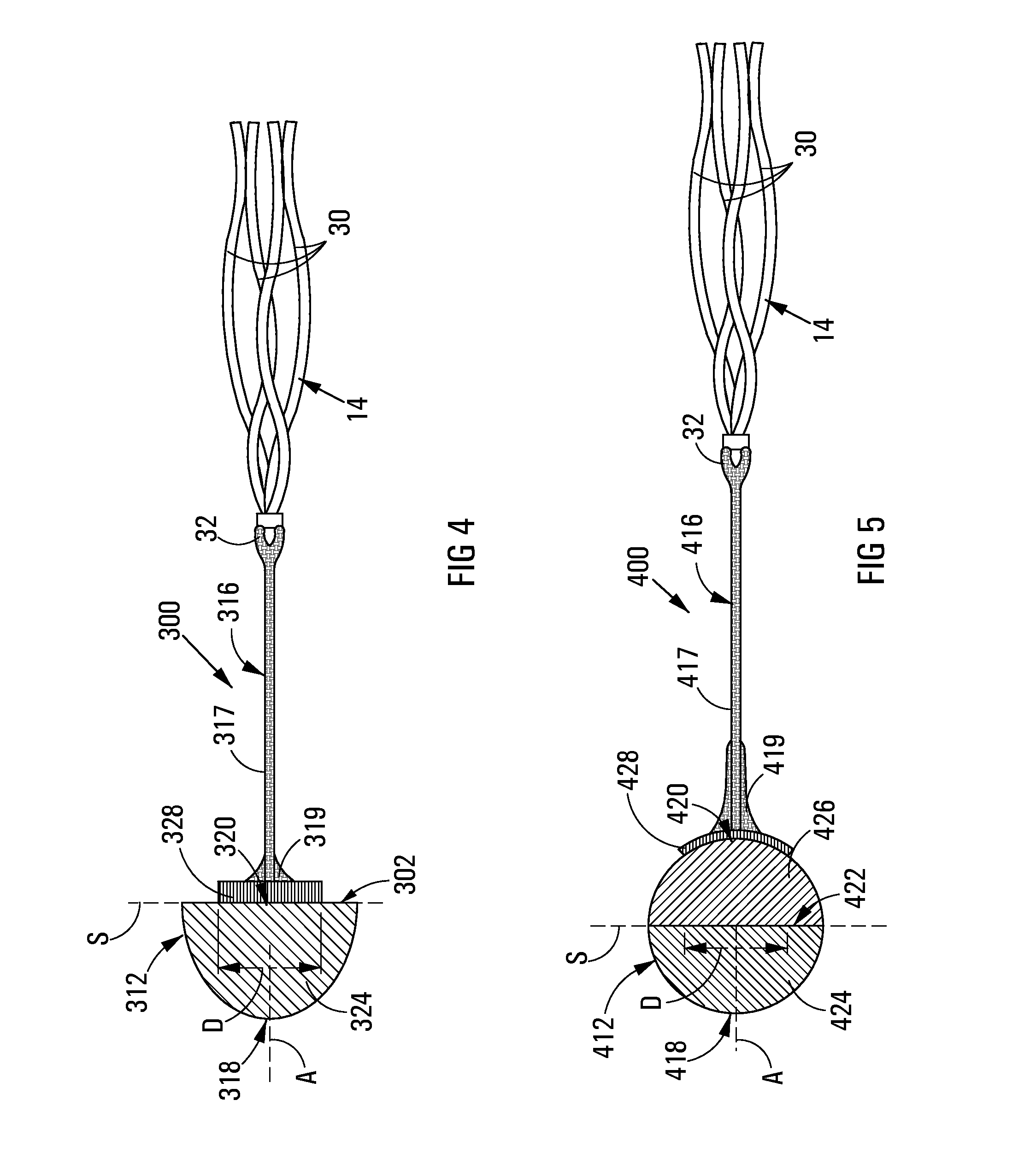
[0054]The streamer ball 100 includes a solid closed cell, homogeneous EVA foam impact body 112 having a hemispherical shape and a spacer stem 116 having a tail 14 attached thereto. The impact body 112 has a leading end 118 and a trailing end 120. The entire impact body 112 is of the same solid foam material which has a density of between 25 kg / m3 and 35 kg / m3 and which is resiliently compressible. The impact body 112 defines a front compression body part 124 which constitutes the frontal impact zone, and a rear ballast body part ...

third embodiment

[0057]With reference to FIG. 3 of the drawings, a streamer ball in accordance with the invention, is designated generally by the reference numeral 200. The streamer ball 200 is similar to the streamer ball 10, with the only difference being the configuration of the impact body. In FIG. 3, the same as and / or similar reference numerals are used to designate those features of the streamer ball 200 which are the same as and / or similar to those of the streamer ball 10.

[0058]The streamer ball 200 includes an impact body 212 having a leading end 218 and a trailing end 220. The impact body comprises a hemispherical front compression body part 224 which constitutes the frontal impact zone of the impact body and a disc-shaped rear ballast body part 226. The front compression body part is of a solid, closed cell homogeneous EVA foam material having a density of between 25 kg / m3 and 35 kg / m3 and a shore Hardness of not more than 25 on the type A durameter scale. The front compression body part ...

fourth embodiment

[0060]With reference to FIG. 4 of the drawings, a streamer ball in accordance with the invention, is designated generally by the reference numeral 400. The streamer ball 400 is similar to the streamer ball 100, with a difference being that the entire spacer stem is disposed externally of the impact body, with the anchor formation of the spacer stem being secured to a rear side of the impact body. As such, in FIG. 4, those features of the streamer ball 300 which are the same as and / or similar to those of the streamer ball 100 are designated by the same and / or similar reference numerals.

[0061]The streamer ball 300 includes an impact body 312 having a leading end 318 and a trailing end 320. The impact body comprises a hemispherical impact compression body 324 which constitutes the frontal impact zone of the impact body. The compression body 324 is of a solid, closed cell homogeneous EVA foam material having a density of between 25 kg / m3 and 35 kg / m3 and a Shore Hardness of not more tha...


PUM


Abstract

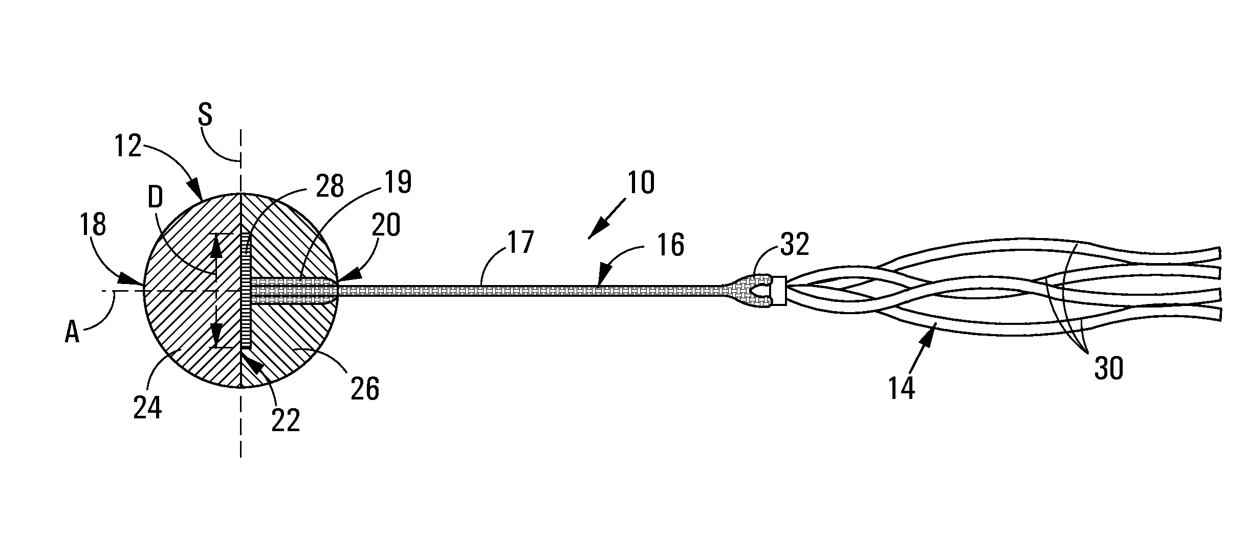
The invention relates to a streamer ball 10 for use in tennis-type bat and bouncing ball games played with bats having rigid, untensioned ball-striking surfaces and comprises an impact body 12, a tail 14 and a spacer stem 16. The impact body comprises a hemispherical front compression body part 24 including a resiliently compressible frontal impact zone; and a hemispherical rear ballast body part 26. The spacer stem includes a stem formation 17, an anchor formation 28 embedded in the rear ballast body part 26 and an attachment formation 32 for the tail comprising elongate streamers which extend rearwardly from the spacer stem in flight. The rear ballast body part has a greater density than that of the front compression body part and the combined mass of the rear ballast body part and the spacer stem provides ballast rearwardly of the front compression body part providing for adequate compression of the frontal impact zone upon impact.

Description

FIELD OF INVENTION[0001]This invention relates to a streamer ball for use in tennis-type bat and ball games wherein the ball is required to bounce on a playing surface.[0002]The streamer ball is configured for use with bats having an untensioned, rigid ball-striking surface. As such, unless otherwise specified, any reference herein to a “bat” must be interpreted to mean a reference to a bat having an untensioned, rigid ball-striking surface.BACKGROUND TO INVENTION[0003]In the context of this specification, a streamer ball is a ball for use in tennis-type ball games of a type having an impact body and a tail comprising a number of elongate flexible streamers which are attached to the impact body for stabilizing the flight orientation of the ball. Streamer balls of this type are known.[0004]A streamer ball of this type is disclosed in U.S. Pat. No. 5,813,931 (assigned to European Sports Merchandising BV). The streamer ball comprises a ball and a tail comprising a number of elongate st...

Claims


Application Information

Patent Timeline
Patent Type & Authority Patents(United States)
IPC IPC(8): A63B43/00
CPCA63B43/00A63B43/007A63B2043/001
Inventor ORR, MOSHE
Owner LIMPET SPORTS MANAGEMENT
Learn More