Trailing arm mounting bracket

a technology for mounting brackets and trailers, which is applied in the direction of resilient suspensions, vehicle springs, understructures, etc., can solve the problems of introducing extra assembly steps, reducing the service life of the vehicle, so as to reduce the number of assembly steps, facilitate manufacturing, and facilitate the effect of taking pla

Inactive Publication Date: 2015-02-24
VDL WEWELER
View PDF24 Cites 11 Cited by
  • Summary
  • Abstract
  • Description
  • Claims
  • Application Information

AI Technical Summary

Benefits of technology

[0011]By providing a vertically oriented mounting plate to which the side plates are mounted, the mounting bracket can easily be mounted to corresponding vertical portions of the chassis or slider assembly, thereby transmitting forces directly to the chassis or slider assembly without using any additional elements. As the centre of the shortest distance between the two openings in the side plates lies substantially in a plane defined by the body of the mounting plate, the force moments applied by the trailing arms to the mounting brackets will be minimal, and preferably also the force moments applied to the chassis and / or the sliding assembly through the mounting plate will be minimal. Therefore no additional reinforcement elements to withstand these force moments are required, resulting in less assembly steps. The mounting bracket therefore provides a light-weight solution for different types of beams used in chassis or slider assemblies.
[0032]In another embodiment, the inwardly located side plate (seen in transverse direction) of the mounting bracket comprises a mounting flange for mounting one end of a strut element to the mounting bracket. The strut element may be provided between opposing side plates of different mounting brackets relating to the same wheel axle or between the side plate and the chassis to provide for additional stiffness in the transverse direction of the vehicle.

Problems solved by technology

Mounting the mounting bracket in alternative ways to, e.g. other types of, beams may not result in an efficient transmittal of forces to the chassis as force moments may be introduced.
However, the reinforcement elements add weight to the vehicle and introduce extra assembly steps.

Method used


Image

  • Trailing arm mounting bracket
  • Trailing arm mounting bracket
  • Trailing arm mounting bracket

Examples


Embodiment Construction

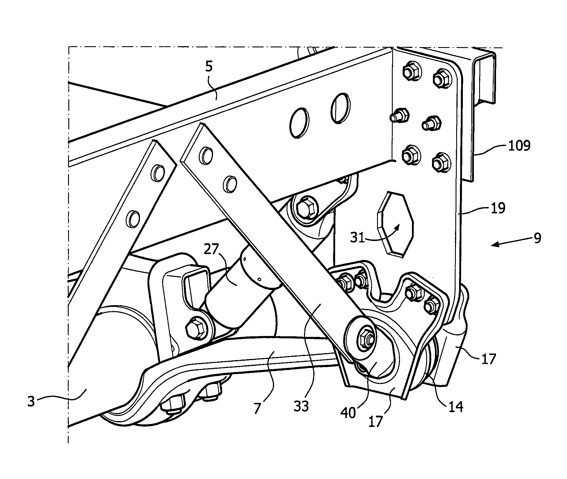
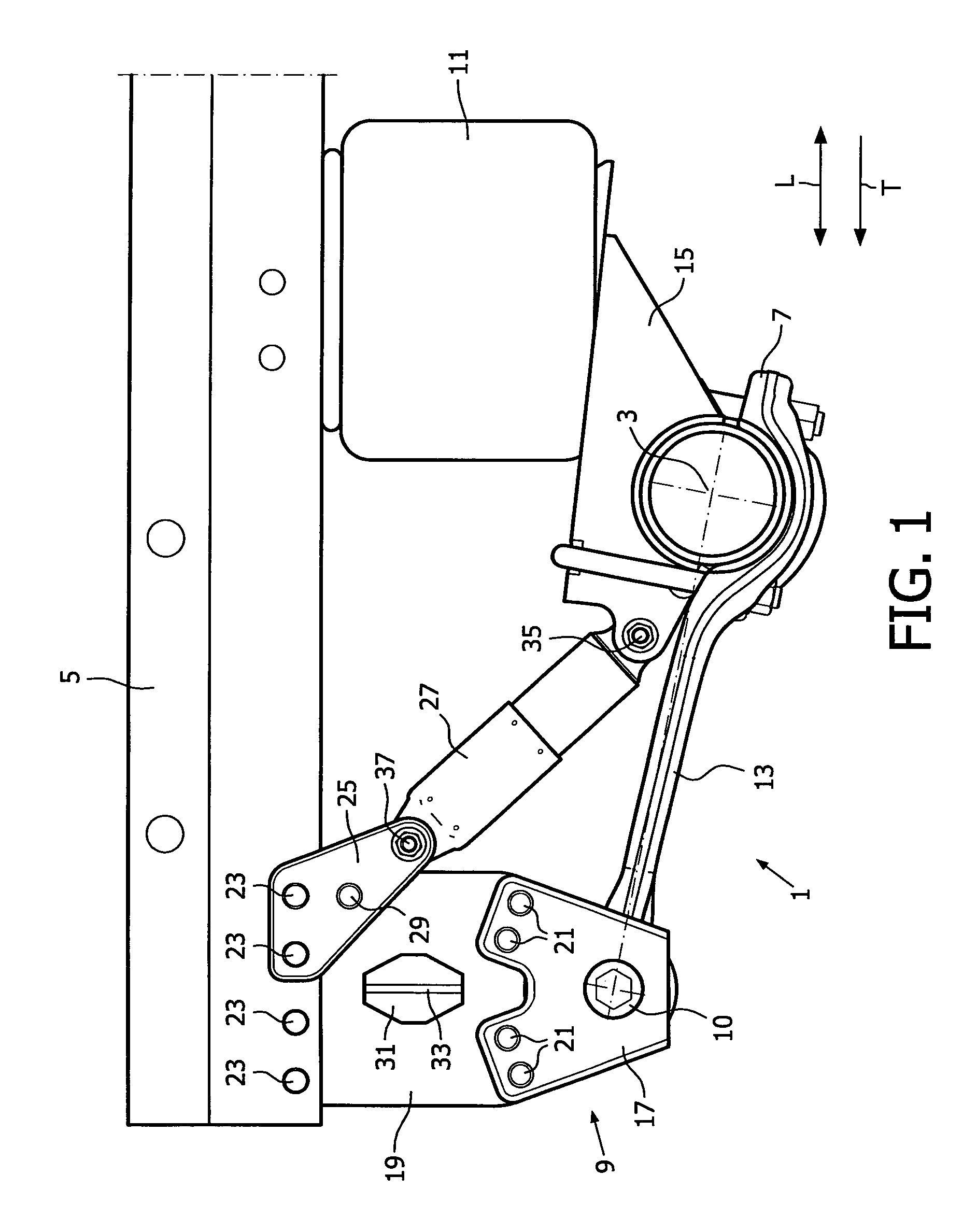
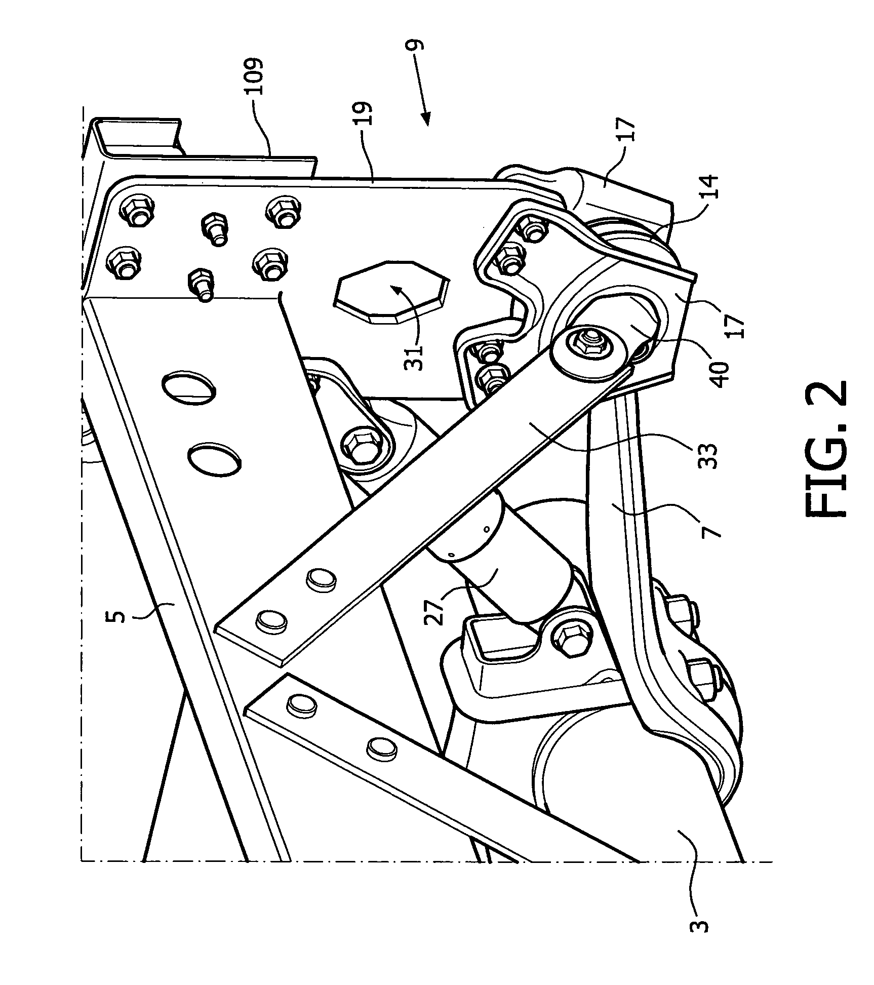
[0056]FIG. 1 depicts a wheel axle suspension 1 according to an embodiment of the invention. The wheel axle suspension 1 is provided between a wheel axle 3 and a chassis 5 of a vehicle. The wheel axle 3 extends in a transverse direction of the vehicle compared to a longitudinal direction L of the vehicle. The wheel axle is mounted to a longitudinal trailing arm 7 extending in the longitudinal direction of the vehicle. The trailing arm 7 is on one end, i.e. its front end seen in the travelling direction T, hingedly connected to a mounting bracket 9 using a hinge pin 10. The other end of the trailing arm is connected to a spring bellow 11 that is connected to the chassis 5.

[0057]In this embodiment, the trailing arm 7 comprises a resilient part 13 and a clamping part 15. Alternatively, the trailing arm can also be a rigid trailing arm. The wheel axle 3 is clamped between the resilient part 13 and the clamping part 15 and thereby connected to the trailing arm 7. The resilient part 13 is ...


PUM


Abstract

A trailing arm mounting bracket for mounting a trailing arm to a chassis or slider assembly of a vehicle, preferably a commercial vehicle, for example a lorry or a lorry trailer, includes two side plates each having a top end, a bottom end, and an opening in the bottom end for receiving a hinge pin, which side plates are positioned opposite each other with their opening at a mutual distance for receiving an end of the trailing arm in between their respective bottom ends, the side plates being mounted with their respective top ends to an in a mounted condition vertically oriented mounting plate, which mounting plate is arranged to connect the mounting bracket to the chassis or slider assembly, and where a center of the shortest distance between the two openings in the side plates lies substantially in a plane defined by the body of the mounting plate.

Description

CROSS-REFERENCE TO RELATED APPLICATIONS[0001]This application is the National Stage of International Application No. PCT / NL2010 / 000057, filed Mar. 25, 2010, the contents of which is incorporated by reference herein.FIELD OF THE INVENTION[0002]The invention relates to the field of wheel axle suspensions. More in particular, the invention relates to a trailing arm mounting bracket for mounting a trailing arm to a chassis of a vehicle, preferably a commercial vehicle, for example a lorry or a lorry trailer.[0003]The trailing arm, also called suspension arm, supports the wheel axle and is hingeably connected at its front end, seen in the direction of travel of the vehicle, to the mounting bracket.[0004]The invention furthermore relates to a wheel axle suspension comprising such a mounting bracket, to a trailer slider assembly provided with such a wheel axle suspension, and to a vehicle provided with such a trailer slider assembly and / or wheel axle suspension.BACKGROUND OF THE INVENTION[...

Claims


Application Information

Patent Timeline
Patent Type & Authority Patents(United States)
IPC IPC(8): B60G7/02B60G9/00B60G11/27B62D21/11
CPCB60G9/003B60G7/02B60G11/27B62D21/11B60G2200/31B60G2202/152B60G2202/24B60G2204/128B60G2204/129B60G2204/143B60G2204/148B60G2204/4302B60G2206/60B60G2206/601B60G2206/722B60G2300/02B60G2300/024B60G2300/026B60G2300/04B60G2300/042
Inventor AALDERINK, DERK GEERT
Owner VDL WEWELER
Why Eureka
Try Eureka