Upper vehicle-body structure of vehicle

a vehicle and upper body technology, applied in the direction of roofs, transportation and packaging, vehicle arrangements, etc., can solve the problems of affecting the welded connection of the mohican portion which is covered with the roof gusset from below, the welding gun may interfere with the roof gusset, and the roof panel may have some strain (deformation), so as to prevent the strain

a vehicle and upper body technology, applied in the direction of roofs, transportation and packaging, vehicle arrangements, etc., can solve the problems of affecting the welded connection of the mohican portion which is covered with the roof gusset from below, the welding gun may interfere with the roof gusset, and the roof panel may have some strain (deformation), so as to prevent the strain

US8960779B2Active Publication Date: 2015-02-24MAZDA MOTOR CORP

Image

  • Upper vehicle-body structure of vehicle
  • Upper vehicle-body structure of vehicle
  • Upper vehicle-body structure of vehicle

Examples


embodiment

[0044]Hereafter, the present embodiment will be described specifically referring to the accompanying drawings. Herein, the terms of directions, such as “front,”“rear,”“longitudinal,”“right,”“left,” or “lateral,” mean respective directions when a proceeding direction of a vehicle is considered as “front”, unless there is any special description on this.

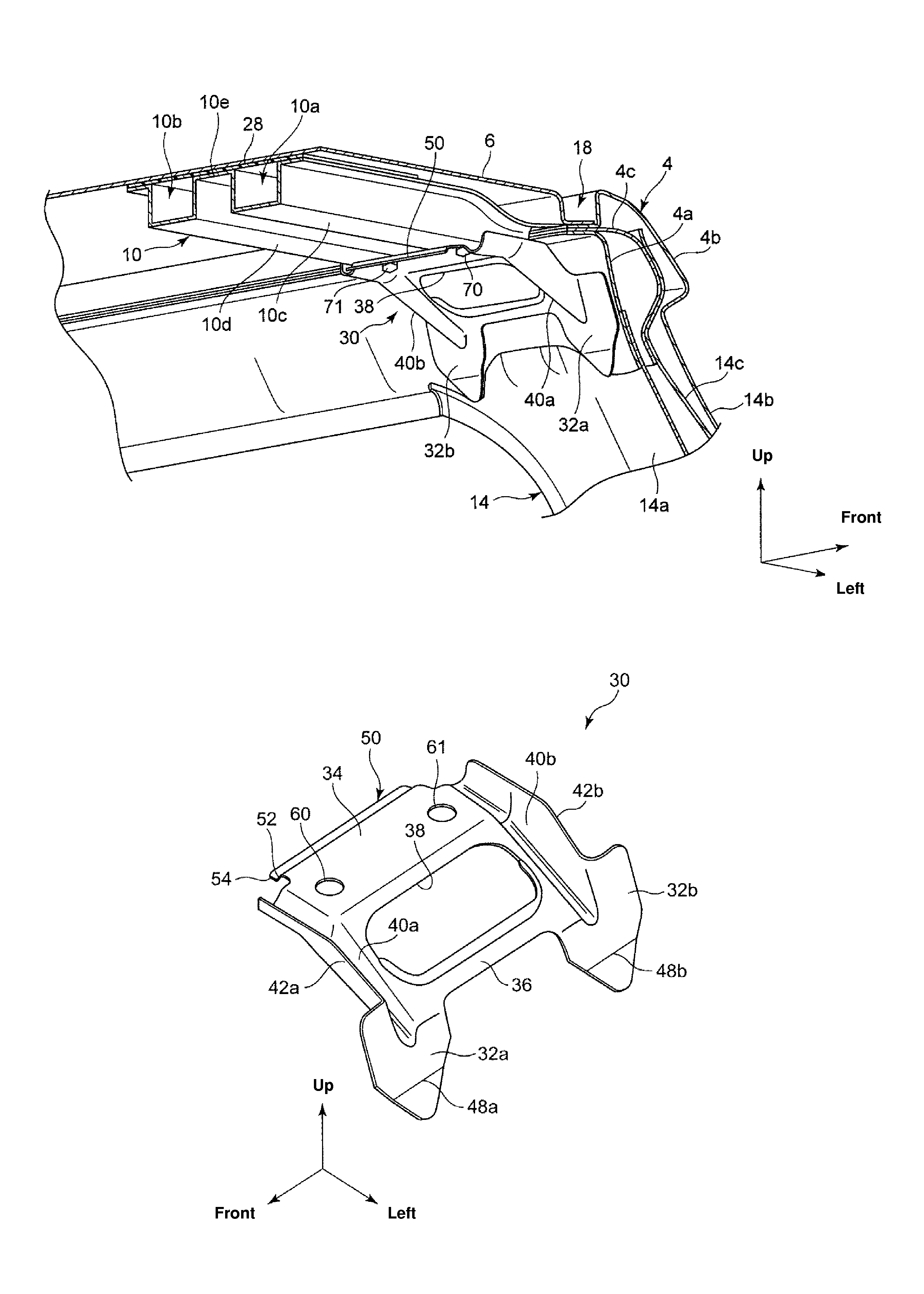
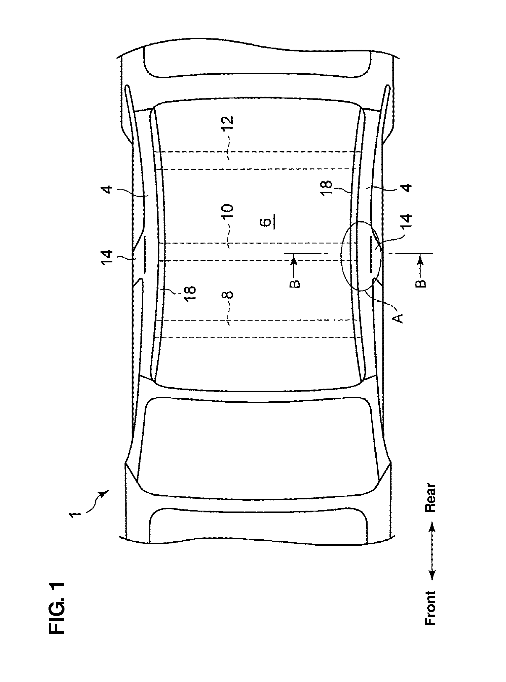
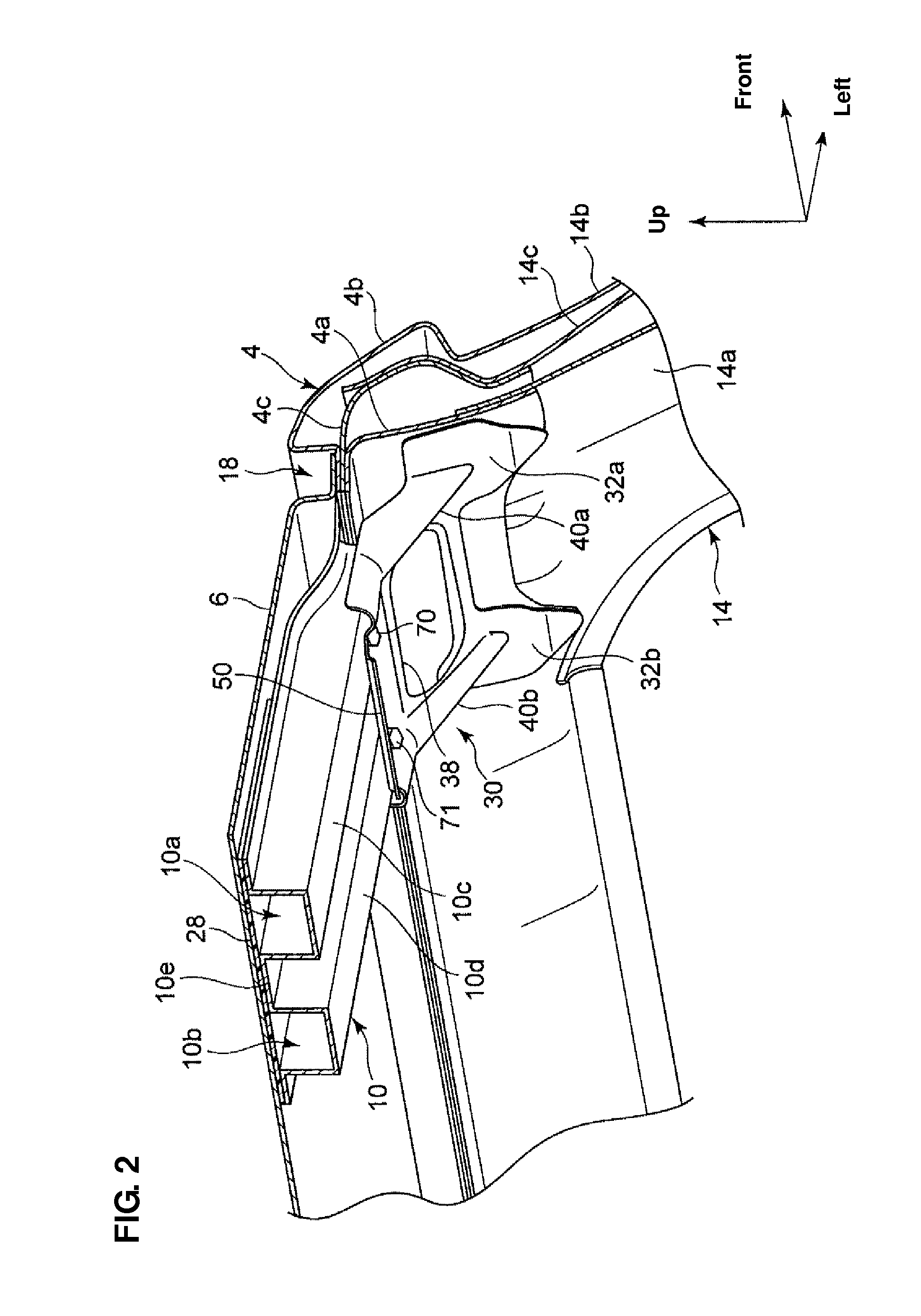
[0045]FIG. 1 is a plan view showing an upper vehicle-body structure of a vehicle 1 according to the present embodiment. As shown in FIG. 1, a pair of roof rails 4 which extends in the vehicle longitudinal direction is provided at both end portions of a roof portion of the vehicle 1, and a center pillar 14 which extends downward from each of the roof rails 4 is joined to a central portion, in the vehicle longitudinal direction, of the roof rail 4.

[0046]Further, plural roof reinforcements 8, 10, 12 which extend in the vehicle width direction are provided between the right-and-left roof rails 4. Specifically, the first roof reinforcement ...


PUM


Abstract

An opening portion is formed at a specified portion of a roof gusset which covers part of a panel joint portion from below. A pair of center-pillar side joint portions is provided at an outward end portion of the roof gusset, which is joined to a center pillar directly or via another panel member. A pair of first high-rigidity portions is provided at specified portions of the roof gusset which overlap the opening portion in a vehicle width direction and overlap the center-pillar joint portions in the vehicle longitudinal direction, respectively. A second high-rigidity portion is provided at an inward end portion of the roof gusset to extend in the vehicle longitudinal direction.

Description

BACKGROUND OF THE INVENTION[0001]The present invention relates to an upper vehicle-body structure of a vehicle, in which a roof gusset is attached so as to extend between a center pillar and a roof reinforcement.[0002]In many automotive vehicles, plural roof reinforcements are provided to extend in a vehicle width direction between right and left roof rails extending in a vehicle longitudinal direction, so that the rigidity of a vehicle-body upper portion can be increased. To an upper face of the roof reinforcements is joined a roof panel by a thermosetting adhesive agent, for example.[0003]Further, in many automotive vehicles, a Mohican-roof structure in which a Mohican portion formed in a groove shape is provided along a roof rail is applied to a roof portion thereof. In the Mohican portion, a flange portion of a roof panel and a flange portion of the roof rail are joined together by spot welding.[0004]Moreover, as disclosed in Japanese Patent Laid-Open Publication No. 2010-221825...

Claims


Application Information

Patent Timeline
24 Feb 2015
Publication
US8960779B2
IPC
B62D25/02; B62D25/06; B62D25/04
CPC
B62D25/06; B62D25/04
Inventors
NISHIMURA, YOSHIKAZU; IKEDA, KEI