Booster seat
a booster seat and seat technology, applied in the field of booster seats, can solve the problems of increasing the volume of the booster seat, not being convenient to store, and no longer being appropriate or needed for infant car seats, and achieve the effects of convenient storage, small volume, and reduced shipment cost of the booster sea
- Summary
- Abstract
- Description
- Claims
- Application Information
AI Technical Summary
Benefits of technology
Problems solved by technology
Method used
Image

Examples
first embodiment
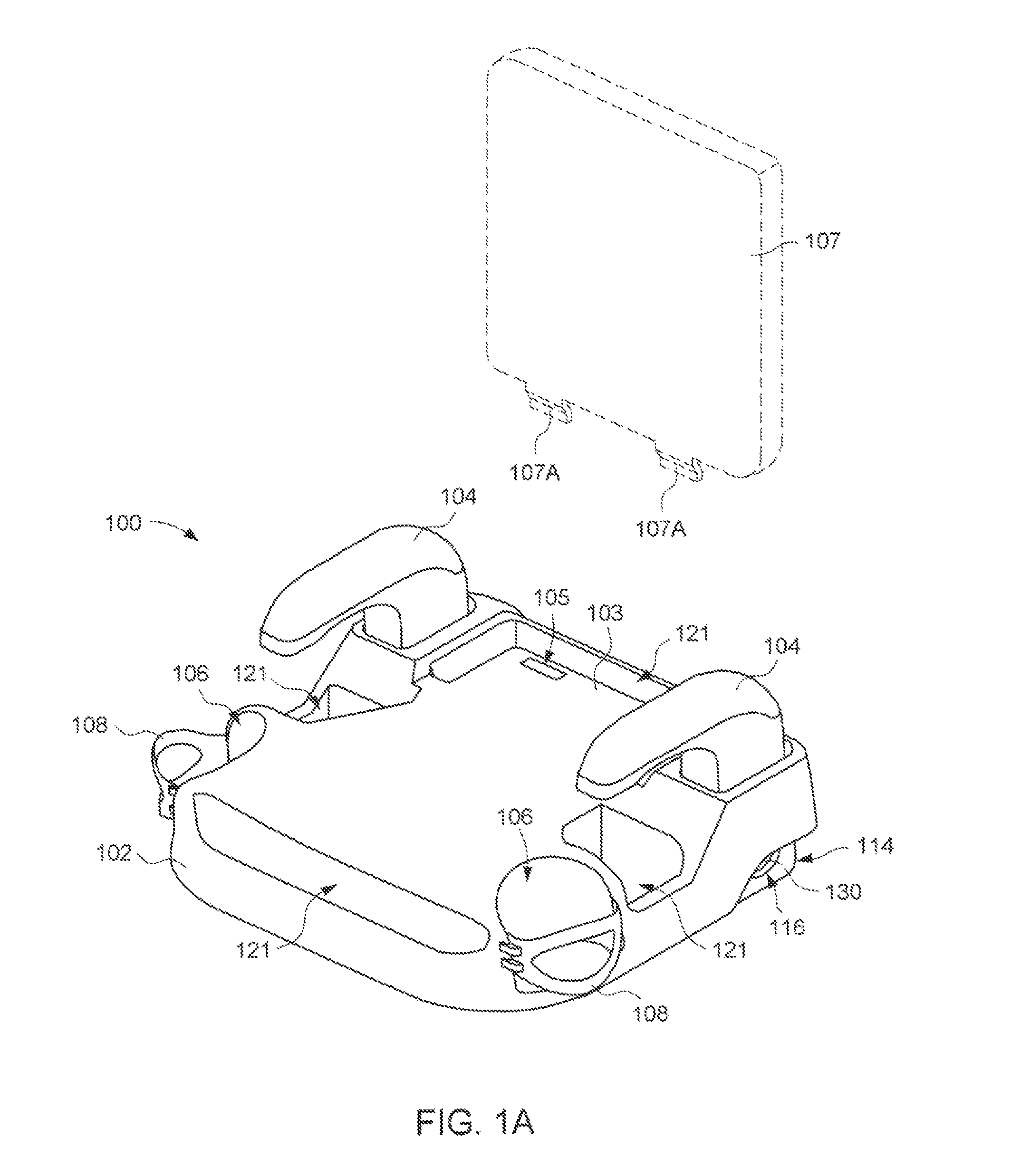
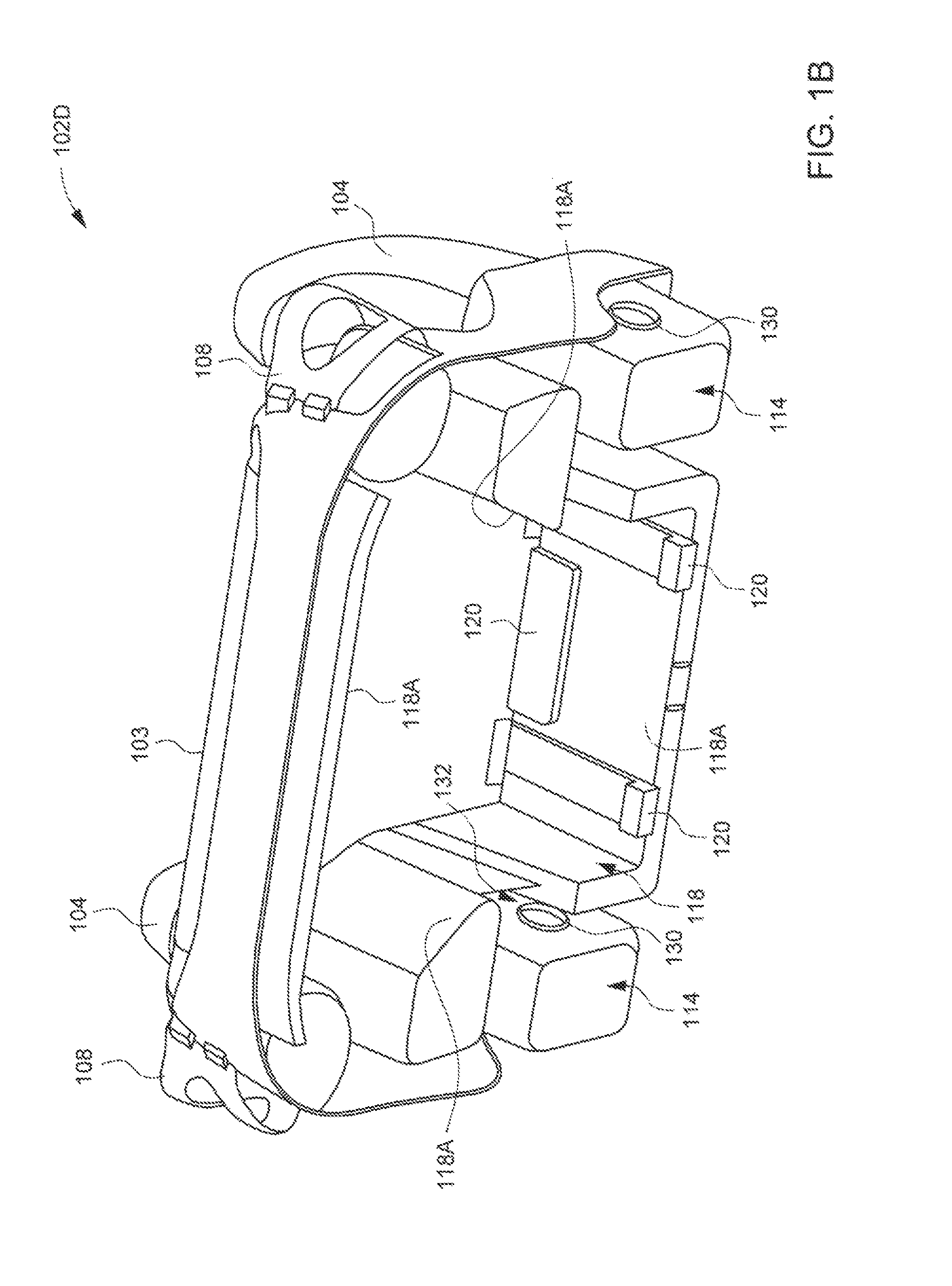
[0036]FIGS. 1A through 1E are schematic views illustrating a child booster seat 100. The booster seat 100 can include a seat shell 102 and armrests 104. The seat shell 102 can be formed in a single body, for example by injection or blow molding of plastic material. The seat shell 102 can have a generally oblong or square shape. The upper side of the seat shell 102 can include a support surface 103 on which a child can be seated. The support surface 103 toward the rear of the seat shell 102 can also include slits 105 through which resilient latches 107A of a backrest 107 (shown with phantom lines) can be engaged to assemble the backrest 107 with the seat shell 102. It is worth noting that the backrest 107 may be provided as an optional accessory that can be removable when unused. While the aforementioned construction uses a specific snap engagement, any attachment structures in general may be suitable to attach the backrest 107 with the seat shell 102.
[0037]Right and left front corne...
second embodiment
[0045]FIGS. 2A through 2C are schematic views illustrating a booster seat 200. The booster seat 200 is generally similar in structure to the embodiment described previously, including a seat shell 202 and armrests 204. The seat shell 202 can be formed in a single body, for example by injection or blow molding of plastic material. The upper side of the seat shell 202 can define a support surface 203 on which a child can be seated. This support surface 203 toward the rear of the seat shell 202 can also include slits 205 for detachably assembling a backrest (not shown). Left and right front corners of the seat shell 202 can respectively include recessed cavities 206 where cup holders 208 can be mounted to hold drinking bottles, cups or like containers. Moreover, right and left sides of the seat shell 202 can respectively include mount sockets 214 for assembling the armrests 204.
[0046]FIG. 2B is a partially enlarged view showing a bottom of the seat shell 202, and FIG. 2C is a partially...
third embodiment
[0051]FIGS. 3A through 3E are schematic views illustrating a booster seat 300. Like the embodiments previously described, the booster seat 300 can include a seat shell 302 and armrests 304. Left and right front corners of the seat shell 302 can be respectively assembled with cup holders 306 to hold drinking bottles, cups or like containers. In addition, the cup holders 306 may also be constructed such that the bottom surface thereof can rest in contact with the seat of the vehicle on which the booster seat 300 is installed. In particular, the bottom surface of each cup holder 306 can be formed with a curved shape that can match with that of the vehicle seat, whereby additional support can be provided to improve stability of the booster seat 300.
[0052]A variety of fastener systems may be used to attach the cup holders 306 with the seat shell 302. FIG. 3D illustrates one example in which each of the cup holders 306 can be formed as a cup-like receptacle having an outer surface provide...
PUM
 Abstract
Description
Claims
Application Information
 - R&D
- Intellectual Property
- Life Sciences
- Materials
- Tech Scout
- Unparalleled Data Quality
- Higher Quality Content
- 60% Fewer Hallucinations
Browse by: Latest US Patents, China's latest patents, Technical Efficacy Thesaurus, Application Domain, Technology Topic, Popular Technical Reports.
© 2025 PatSnap. All rights reserved.Legal|Privacy policy|Modern Slavery Act Transparency Statement|Sitemap|About US| Contact US: help@patsnap.com