Range-change transmission with an electric engine

a transmission device and electric motor technology, applied in mechanical equipment, transportation and packaging, gearshifts in automated group transmissions, etc., can solve the problems of only being able to operate with the least brief interruption of the traction force applied at the drive output, only being able to carry out gearshifts with traction force interruption, etc., to save structural fitting space, operate with little effort and complexity, and be inexpensive and simple to design

Inactive Publication Date: 2015-02-24
ZF FRIEDRICHSHAFEN AG
View PDF23 Cites 20 Cited by
  • Summary
  • Abstract
  • Description
  • Claims
  • Application Information

AI Technical Summary

Benefits of technology

[0008]Thus the purpose of the present invention is to provide a group transmission device having an electric machine, which saves structural fitting space, is inexpensively and simply designed and can be operated with little effort and complexity, by means of which as many gearshifts as possible can be carried out without traction force interruption.
[0016]Then, besides the gearshifts that can be power-shifted in the area of the splitter group by means of the group transmission device according to the invention in combination with the electric machine, other known hybrid functions can also be implemented. For example, purely electric driving operation of a vehicle drive-train constructed with the group transmission device according to the invention, and starting of a drive engine of a vehicle drive-train, preferably in the form of an internal combustion engine connected to the transmission input shaft of the group transmission device, by means of the electric machine, are possible. In addition an electric accumulator associated with the electric machine can be charged in a simple manner when the electric machine is operated as a generator, and boosting operation or a load point displacement can be realized. Furthermore the main transmission can also be synchronized by the electric machine and purely electric starting operation and an electrodynamic starting process can be carried out, during which a drive torque of a drive engine coupled to the transmission input shaft in the area of the electric machine is assisted.
[0025]If the further shifting element is positioned between the planetary transmission device and the gear step of the splitter group that is or can be connected to the second shaft, the further shifting element can be arranged outside a transmission housing containing the splitter group, the main transmission and the range group. It is then possible to use a transmission housing of a transmission in which the splitter group, the main transmission and the range group are combined with a dual clutch system. The transmission housing that can then be used is an inexpensive modular standard component.
[0026]Alternatively, in a further embodiment of the group transmission device according to the invention it is provided that the further shifting element is arranged on the side of the splitter group gear that is or can be connected to the second shaft, which faces away from the planetary gearset. In this embodiment of the group transmission device the further shifting element can be integrated in the transmission housing in a simple manner and the group transmission device according to the invention can then occupy less axial fitting space.
[0027]In other advantageous embodiments of the group transmission device according to the invention, the further shifting element is an inexpensive interlocking shifting element or a frictional shifting element, and when in the form of a frictional shifting element the further shifting element can also be opened or closed under load and, for example, during a sharp deceleration of a vehicle stalling of an internal combustion engine can be avoided simply by opening the further shifting element.

Problems solved by technology

Disadvantageously, gearshifts in automated group transmissions can only be carried out with traction force interruption, when the gearshift required can be carried out as a range shift in the area of the splitter group with corresponding assistance from the electric machine.
This means that gearshifts are in each case only possible without traction force interruption between two adjacent gears.
However, this results in an at least brief interruption of the traction force applied at the drive output.
For well known reasons traction force interruptions are undesired, particularly in the case of utility vehicles such as trucks or the like, and especially when driving uphill and downhill.

Method used


Image

  • Range-change transmission with an electric engine
  • Range-change transmission with an electric engine
  • Range-change transmission with an electric engine

Examples


Embodiment Construction

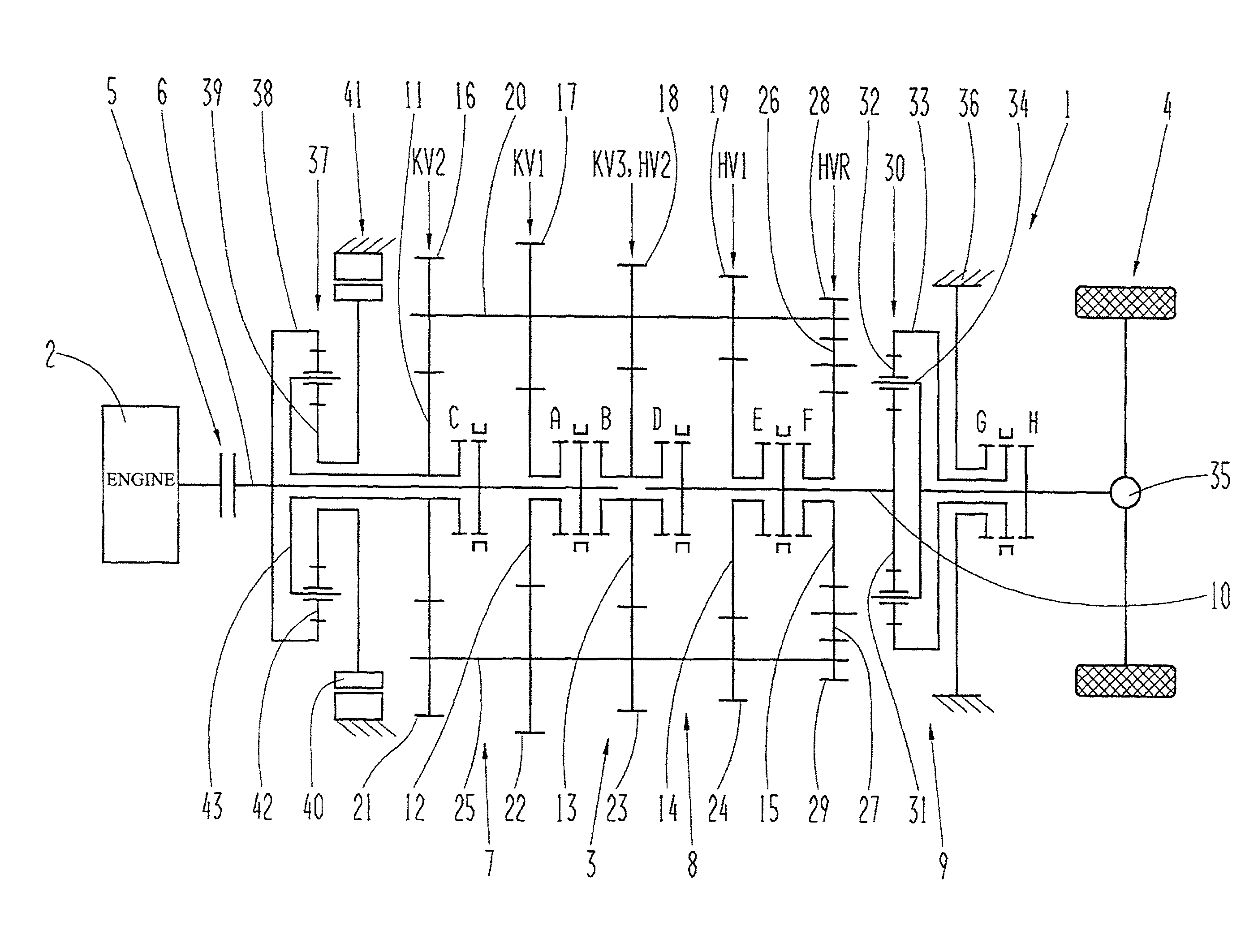
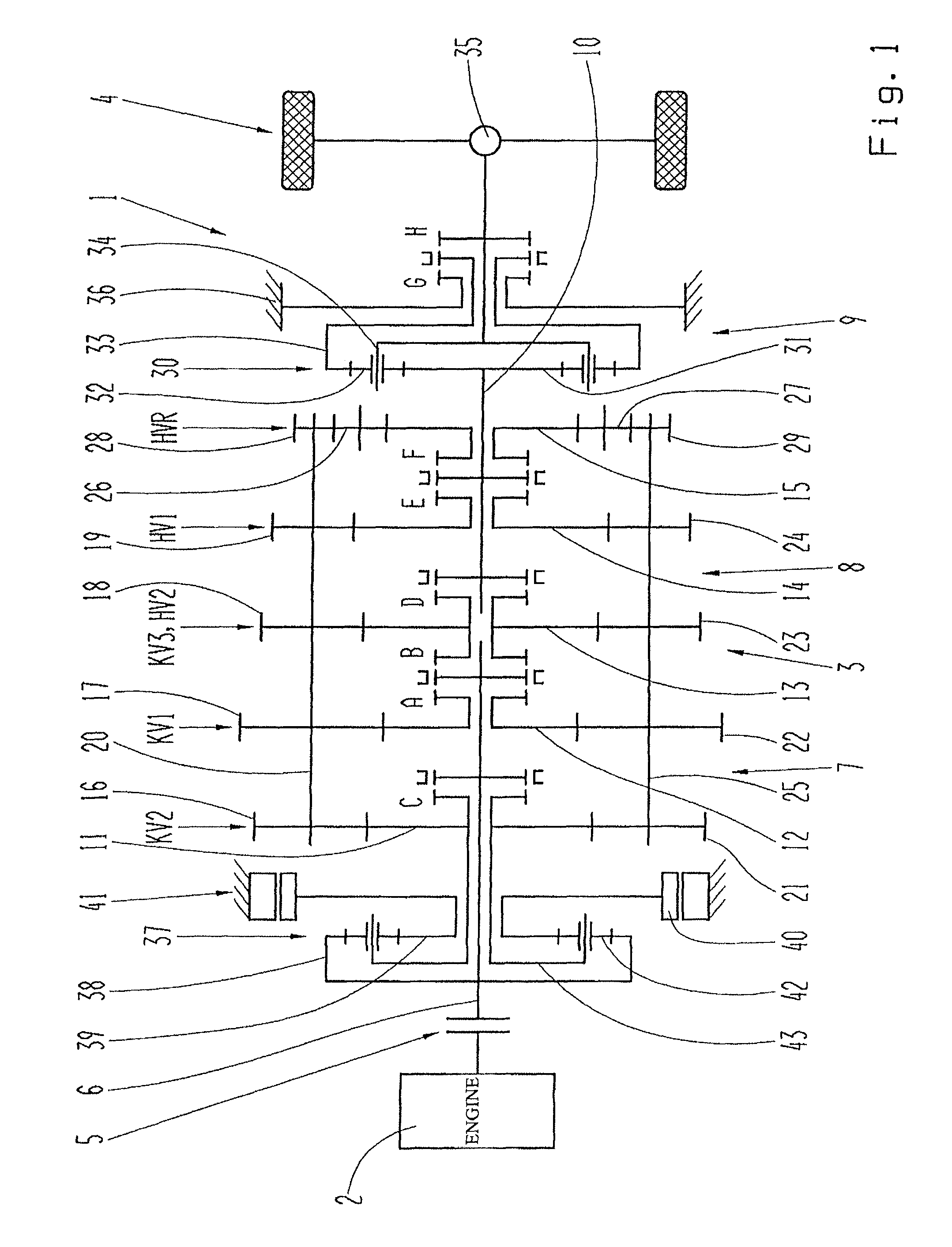
[0044]FIG. 1 shows a vehicle drive-train 1 with a drive engine 2, a group transmission device 3 and a drive output 4. In this case the drive engine 2 is in the form of an internal combustion engine but in other embodiments of the vehicle drive-train 1 it can also be in the form of an electric machine or a combination of an internal combustion engine and an electric machine. Between the drive engine 2 and the group transmission device 3 there is arranged in this case a starting clutch 5 in the form of a friction clutch by means of which, when in the closed operating condition, the drive engine 2 is connected in a rotationally fixed manner to a transmission input shaft 6.

[0045]The group transmission device 3 comprises three transmission groups. On the transmission input side in this case there is a three-step upstream group 7 designed as a splitter group, which is of countershaft design. In addition the group transmission device 3 is configured with a main transmission 8 connected in ...


PUM


Abstract

A group transmission device with an electric machine, a main transmission of a countershaft design, a splitter group of a countershaft design which is connected upstream of the main transmission and a range group connected downstream of the main transmission. In the area of the main transmission, the splitter group, and the range group, a gear ratio is variable by gear steps that can be engaged in, or disengaged from, the force flow by interlocking shifting elements. At least during a gearshift, torque of the electric machine can be introduced into the force flow in the area of the splitter group. The splitter group has at least three gear steps that can be engaged or disengaged, the main transmission has at least two gear steps that can be engaged or disengaged, and the range group has at least two gear steps that can be engaged and disengaged.

Description

[0001]This application claims priority from German patent application serial no. 10 2012 218 367.1 filed Oct. 9, 2012.FIELD OF THE INVENTION[0002]The invention concerns a range-change transmission device with an electric machine.BACKGROUND OF THE INVENTION[0003]From the unpublished document DE 10 2011 080 069.7 by the present applicant, a range-change transmission device designed as an automated range-change transmission of a motor vehicle is known, which has a three-step main transmission of countershaft structure. In driving connection upstream from the main transmission is a two-step upstream transmission designed as a splitter group and downstream from the main transmission there is connected a two-step range group. An input shaft of the group transmission can be brought into functional connection with a drive aggregate of the motor vehicle and an output shaft of the group transmission can be brought into functional connection with an axle drive of the motor vehicle. An electric...

Claims


Application Information

Patent Timeline
Patent Type & Authority Patents(United States)
IPC IPC(8): F16H3/72F16H3/093F16H3/12F16H3/62F16H37/04
CPCF16H3/62F16H3/126F16H37/046F16H37/042F16H2003/0931F16H2200/0091F16H2200/0078
Inventor KALTENBACH, JOHANNESMITTELBERGER, CHRISTIAN
Owner ZF FRIEDRICHSHAFEN AG
Why Eureka
Try Eureka