
Separator assembly

a technology of separation assembly and assembly plate, which is applied in the direction of membrane technology, separation process, membrane, etc., can solve the problems of loss of membrane function and uncontrolled contact, and achieve the effect of efficient and cost-effectiv

Active Publication Date: 2015-02-24
BL TECH INC
View PDF42 Cites 10 Cited by
  • Summary
  • Abstract
  • Description
  • Claims
  • Application Information

AI Technical Summary

Benefits of technology

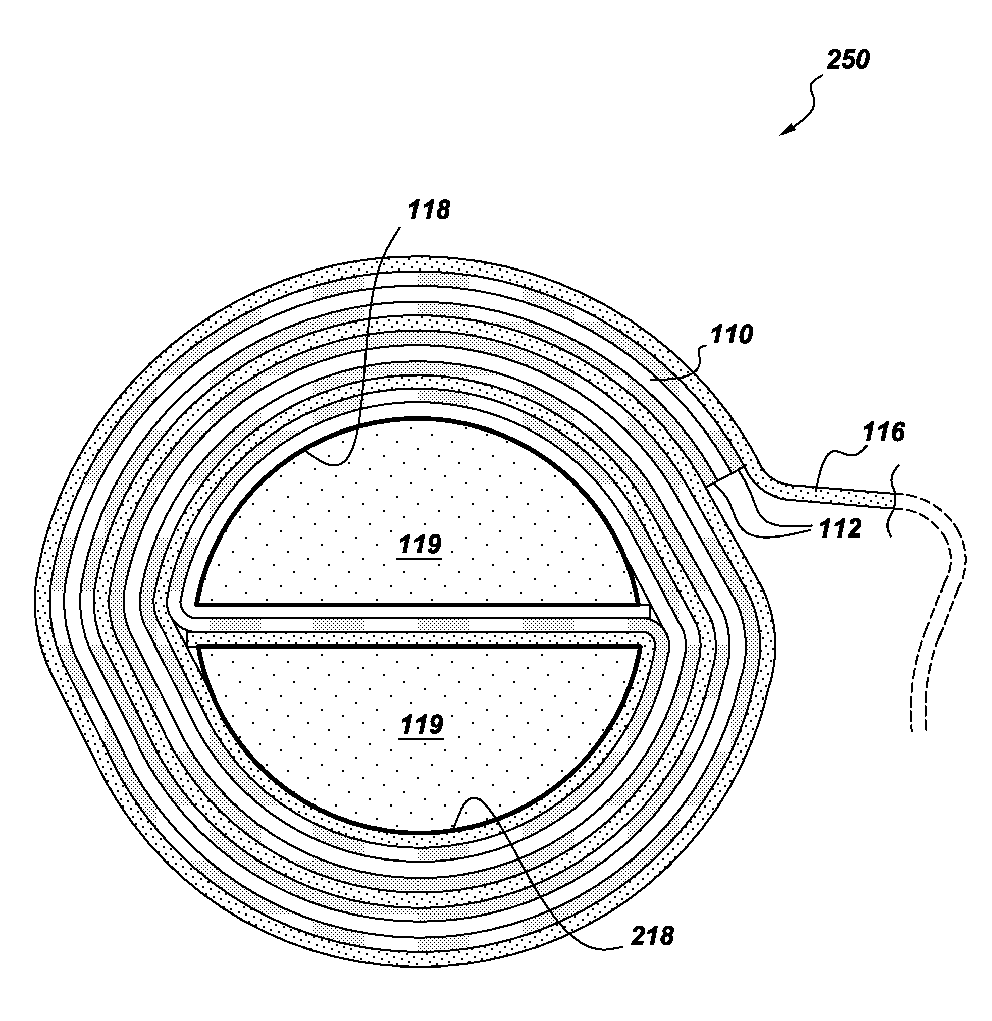
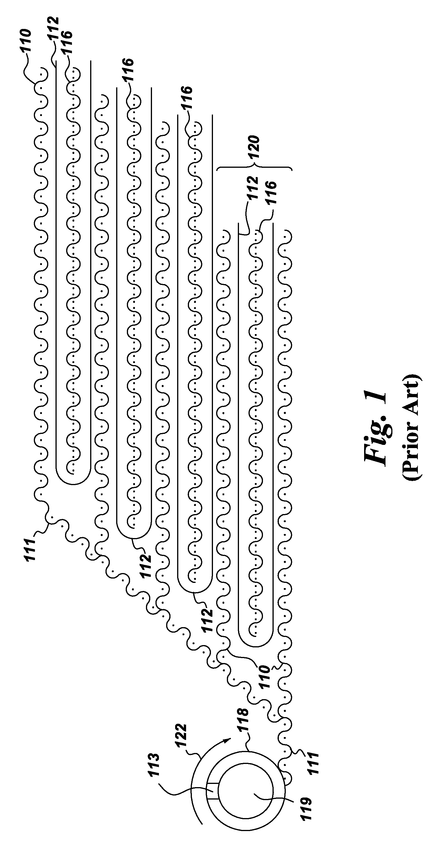
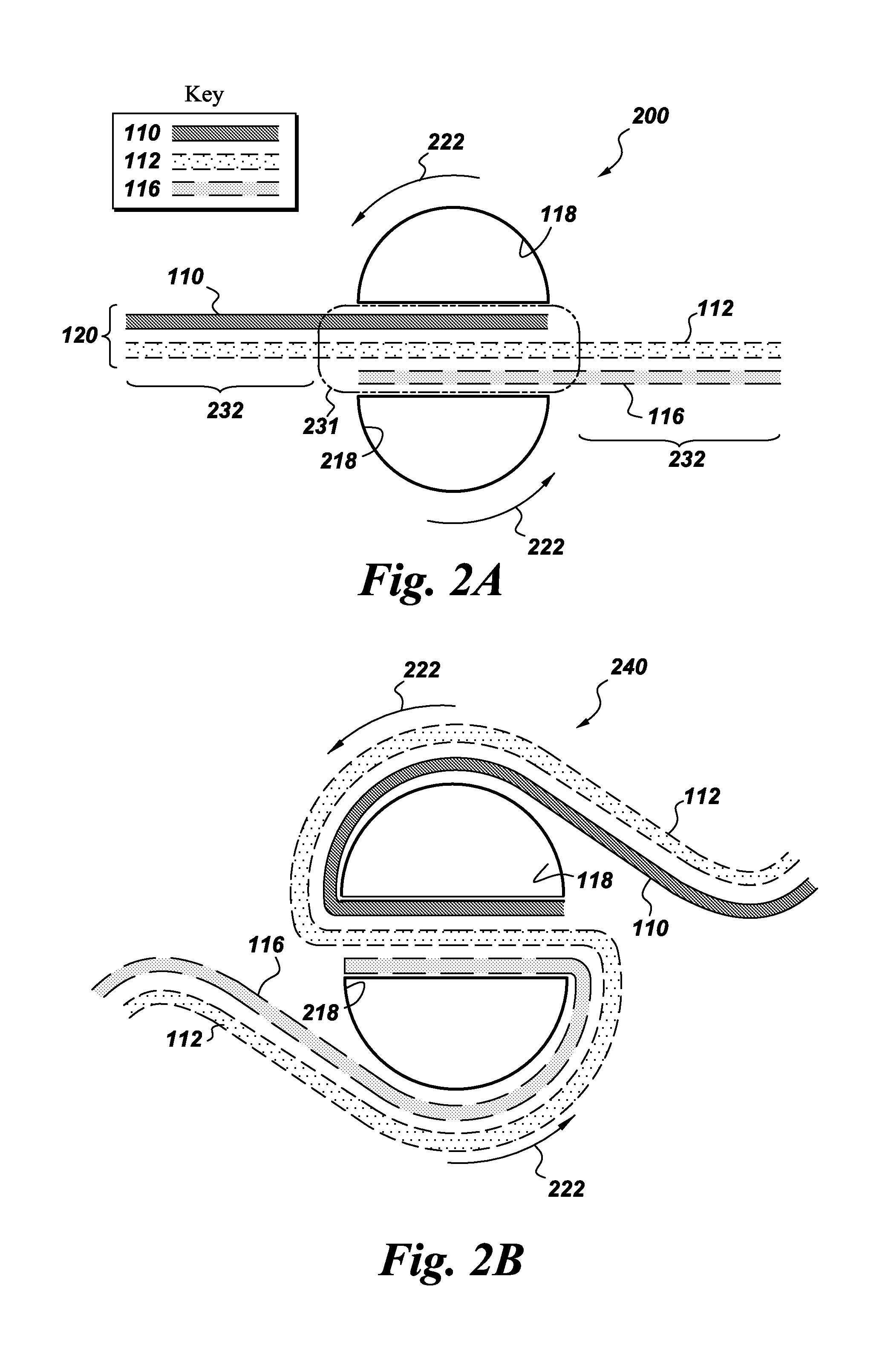
The present invention provides a separator assembly and a membrane stack assembly for use in a spiral flow reverse osmosis apparatus. The separator assembly includes a central core element with at least one permeate exhaust conduit and at least one concentrate exhaust conduit, which define an exhaust channel and openings for fluid communication. The membrane stack assembly includes at least one feed carrier layer, at least one permeate carrier layer, and at least one membrane layer. The first portion of the membrane stack assembly is disposed within the cavity defined by the central core element, and the second portion forms a multilayer membrane assembly around the central core element. The technical effects of the invention include improved membrane utilization, reduced membrane fouling, and improved separation efficiency.

Problems solved by technology

A serious weakness separator assemblies comprising a folded multilayer membrane assembly is that the folding of the membrane layer may result in loss of membrane function leading to uncontrolled contact between the feed solution and the permeate carrier layer.

Method used


Image

  • Separator assembly
  • Separator assembly
  • Separator assembly

Examples


Embodiment Construction

[0035]In the following specification and the claims, which follow, reference will be made to a number of terms, which shall be defined to have the following meanings.

[0036]The singular forms “a”, “an”, and “the” include plural referents unless the context clearly dictates otherwise.

[0037]“Optional” or “optionally” means that the subsequently described event or circumstance may or may not occur, and that the description includes instances where the event occurs and instances where it does not.

[0038]Approximating language, as used herein throughout the specification and claims, may be applied to modify any quantitative representation that could permissibly vary without resulting in a change in the basic function to which it is related. Accordingly, a value modified by a term or terms, such as “about” and “substantially”, are not to be limited to the precise value specified. In at least some instances, the approximating language may correspond to the precision of an instrument for meas...


PUM

PropertyMeasurementUnit
reflex angleaaaaaaaaaa

Abstract

A novel separator assembly for a spiral flow reverse osmosis apparatus is provided. In one embodiment, the separator assembly comprises a central core element comprising at least one permeate exhaust conduit and at least one concentrate exhaust conduit. Each exhaust conduit defines an exhaust channel and one or more openings allowing fluid communication between an exterior surface of the exhaust conduit and the exhaust channel, said exhaust conduits independently defining a cavity between said conduits. The cavity is configured to accommodate a first portion of a membrane stack assembly comprising at least one feed carrier layer, at least one permeate carrier layer, and at least one membrane layer. A first portion of the membrane stack assembly is disposed within the cavity, and a second portion of the membrane stack assembly is wound around the central core element and forms a multilayer membrane assembly disposed around the central core element.

Description

CROSS REFERENCE TO RELATED APPLICATIONS[0001]This Application claims the benefit of and is a Continuation-In-Part of U.S. patent application Ser. No. 12 / 330,536 filed Dec. 9, 2008, said U.S. patent application claiming priority to U.S. Provisional Application No. 61 / 106,219 filed Oct. 17, 2008 and U.S. Provisional Application No. 61 / 111,366 filed Nov. 5, 2008, and further claims the benefit of and is a Continuation-In-Part of U.S. patent application Ser. No. 13 / 149,448 filed May 31, 2011 and U.S. patent application Ser. No. 13 / 157,705 filed Jun. 10, 2011; each of which named applications and Provisional Application is herein incorporated by reference in its entirety. Where subject matter present in any of the matter incorporated by reference is in conflict with subject matter in the present application, the present application will be considered authoritative.BACKGROUND[0002]This invention includes embodiments that generally relate to separator assemblies. In various embodiments, th...

Claims


Application Information

Patent Timeline
Patent Type & Authority Patents(United States)
IPC IPC(8): B01D63/06B01D63/10B01D63/12C02F1/44C02F103/08
CPCB01D63/10B01D63/103C02F1/441B01D2313/10B01D2313/12C02F2103/08Y02A20/131B01D63/107B01D63/1031
Inventor BEAUCHAMP, PHILIP PAULCUEMAN, MICHAEL KENTERNO, DANIEL JASONANDERSON, TODD ALANMARSCHKE, DEAN DAVID
Owner BL TECH INC
Learn More