Coupling structure of fuel assembly

a fuel assembly and coupling technology, applied in nuclear engineering problems, nuclear elements, greenhouse gas reduction, etc., can solve the problem of not being able to be easily detached and attached in the power plan

Active Publication Date: 2015-02-24
MITSUBISHI HEAVY IND LTD
View PDF16 Cites 0 Cited by
  • Summary
  • Abstract
  • Description
  • Claims
  • Application Information

AI Technical Summary

Benefits of technology

[0014]According to the present invention, a coupling structure of a fuel assembly is achieved which eliminates a factor leading to mixing of a detached component in the fuel assembly since there is no need to disassemble the components at the time of attachment and detachment of the upper nozzle, and in which no vertical play is generated at an attachment / detachment portion of the upper nozzle.

Problems solved by technology

However, the upper nozzle 101 is conventionally joined to the sleeves 107 by welding as described above, and therefore, cannot be easily detached and attached in the power plant.

Method used


Image

  • Coupling structure of fuel assembly
  • Coupling structure of fuel assembly
  • Coupling structure of fuel assembly

Examples


embodiment 1

[0042]Next, described is a coupling structure of a fuel assembly according to the first embodiment of the present invention.

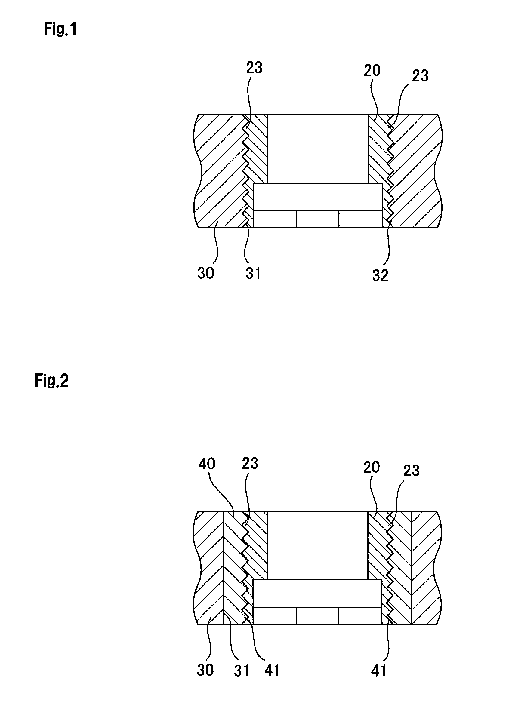
[0043]As shown in FIG. 1, the male screw thread 23 is formed on the side surface of the lock key 20. A female screw thread 32 is formed on an inner surface of the latch sleeve installation hole 31 of the upper nozzle 30. The lock key 20 is installed inside the latch sleeve installation hole 31, and the lock key 20 and the latch sleeve installation hole 31 are screw-coupled to each other.

[0044]According to the present embodiment described above, the coupling of the lock key 20 and the latch sleeve 10 (see FIG. 6) can be released and the upper nozzle 30 can thus be detached, without completely detaching the lock key 20 from the latch sleeve installation hole 31. Accordingly, there is no need to disassemble components at the time of attaching and detaching the upper nozzle 30. Thereby, a factor leading to mixing of a detached component in the fuel assembly is elim...

embodiment 2

[0046]Next, described is a coupling structure of a fuel assembly according to the second embodiment of the present invention.

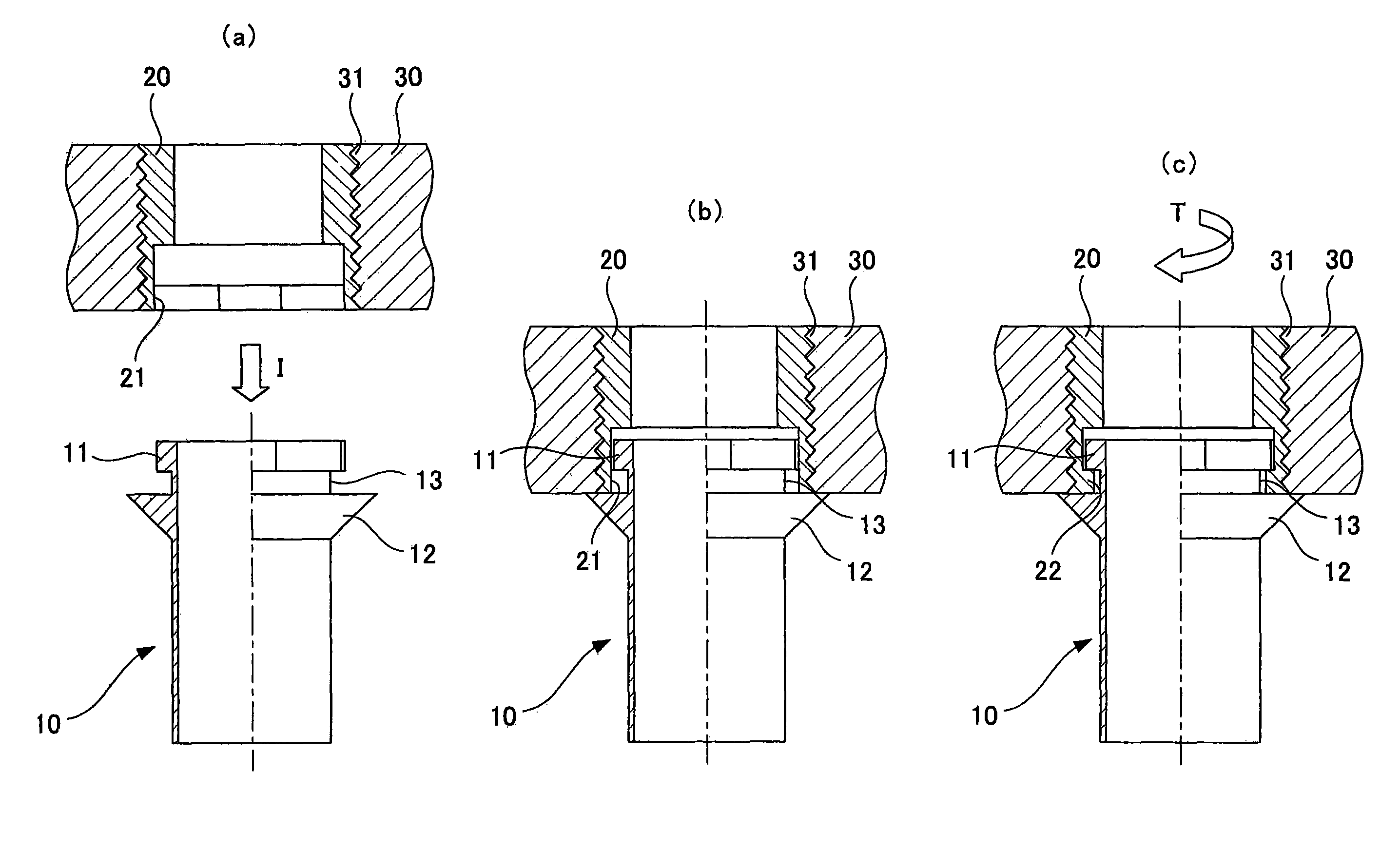
[0047]Firstly, a background of the present embodiment will be described. In the above described coupling structure of the fuel assembly according to the first embodiment, when coupled to or released from the latch sleeve 10, the lock key 20 moves up and down vertically by being rotated along the female screw thread 32 formed on the inner surface of the latch sleeve installation hole 31.

[0048]Accordingly, in order for the vertical play not to be generated at the time of the coupling of the lock key 20 and latch sleeve 10, there is a need to adjust at least a processing start position for the female screw thread 32 formed on the inner surface of the latch sleeve installation hole 31 of the upper nozzle 30.

[0049]Moreover, when the upper nozzle 30 is attached as the fuel assembly, not to allow the play to be generated at the time of the coupling, the processing st...

embodiment 3

[0054]Next, described is a coupling structure of a fuel assembly according to a third embodiment of the present invention.

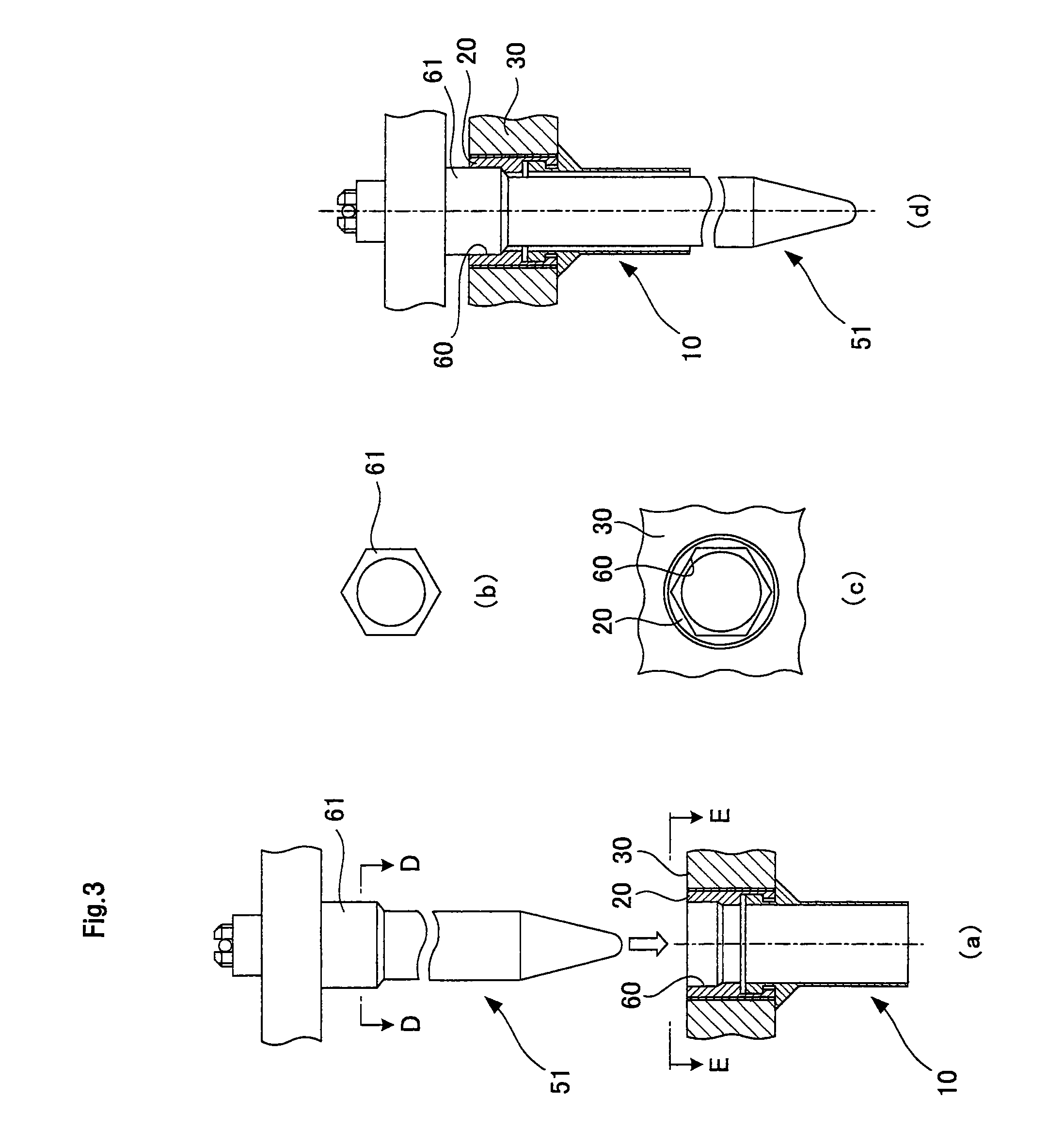
[0055]The lock key 20 according to the above described first and second embodiments has the following problem. When the lock key 20 rotates due to some reason and becomes loose, the fitting portion between the lock key 20 and the latch sleeve 10 may be released or the vertical play may be generated. To solve this problem, a rotation prevention structure needs to be provided for the lock key 20 to prevent the lock key 20 from rotating and becoming loose.

[0056]As the rotation prevention structure, conventional industrial methods such as caulking, pinning, and welding may be used. However, when these methods are used, quick attachment (preventing the lock key 20 from becoming loose) and detachment of the upper nozzle 30 cannot be performed in the power station or the like. To solve this problem, in the present embodiment, a later described reel hole 60 (see FIG. 3) ...


PUM


Abstract

A coupling structure of a fuel assembly includes a screw coupling means to provide a coupling structure of a fuel assembly which prevents foreign matters from mixing in the fuel and in which no vertical play is generated at a fitting portion between a latch sleeve 10 and a lock key 20. The coupling structure of the fuel assembly includes: the latch sleeve 10 having a projecting portion 11 formed at an upper end portion thereof; an upper nozzle 30 having formed therein a latch sleeve installation hole 31 into which the upper end portion of the latch sleeve 10 is inserted; and the lock key 20 which is installed inside the latch sleeve installation hole 31, and which has an opening portion 21 formed on a bottom surface thereof, the opening portion 21 having a shape corresponding to the projecting portion 11. The screw coupling means screw couples the lock key 20 to the upper nozzle 30 with a male screw thread 23 formed on a side surface of the lock key 20.

Description

FIELD OF INVENTION[0001]The present invention relates to a coupling structure of a fuel assembly.BACKGROUND ART[0002]As shown in FIG. 11, a fuel assembly of a pressurized-water nuclear reactor is configured of fuel rods 100, an upper nozzle 101, a lower nozzle 102, guide tubes 103, an upper support lattice 104, an intermediate support lattice 105, a lower support lattice 106, and a foreign matter filter. The upper support lattice 104 and the intermediate support lattice 105 are mechanically joined to the guide tubes 103, and the lower support lattice 106 is mechanically joined to lower ends of the guide tubes 103 together with the lower nozzle 102. The upper support lattice 104, the intermediate support lattice 105, and the lower support lattice 106 hold the fuel rods 100. As shown in FIG. 12, the upper nozzle 101 is joined, by welding, to upper end portions 108 of sleeves 107 attached to the upper support lattice 104. Moreover, the sleeves 107 and the guide tubes 103 are mechanical...

Claims


Application Information

Patent Timeline
Patent Type & Authority Patents(United States)
IPC IPC(8): G21C3/32G21C3/33G21C3/334
CPCG21C3/334G21C3/3315G21Y2002/303G21Y2002/304G21Y2004/301Y02E30/40Y02E30/30
Inventor HARADA, HIDENORIYAMADA, MASAHIKO
Owner MITSUBISHI HEAVY IND LTD
Why Eureka
Try Eureka