Plate and screws for treatment of bone fractures

a technology of bone fractures and screws, applied in the field of plate and screws for bone fracture treatment, can solve the problems of reducing the periosteal blood supply, reducing the stability, and reducing so as to reduce the stress and eliminate the potential contact between the plate and the bone

Active Publication Date: 2015-03-03
KYON
View PDF31 Cites 47 Cited by
  • Summary
  • Abstract
  • Description
  • Claims
  • Application Information

AI Technical Summary

Benefits of technology

[0022]The purpose of the recess is to eliminate the potential contact of the plate and the bone surrounding the screw. The lower surface of the plate is essentially planar.
[0023]Said recesses are preferably of approximately annular form. While the shape of the recess may be circular in shape when viewed from the lower side of the plate, other shapes can be used to achieve the same effect. A shape somewhat elongated in the direction of the long axis of the plate can be used to reduce the stresses at the transverse aspect of the plate along the remaining lower surface. The recess can also be rounded at its base and / or faceted at its edge as one skilled in art would do to avoid stress concentrations at sharp corners, or injuries at sharp edges.
[0027]Preferably, the transverse grooves are positioned between at least some of the holes, preferably on the lower, bone facing side of the plate. Transverse grooves may also be present on the upper side of the plate. Preferably, there is one or more transverse groove between any two holes. Transverse grooves may also be cut into the plate from the sides, or the sides may comprise side cuts which reduce the width of the plate between the holes.
[0033]The geometry of said plate may further be modified by side cuts, spaced between at least some of the holes. In many uses of bone plates, it is desirable to bend the plate in both planes. So-called reconstruction plates with deep side cuts do exist, but those are intended for use in less loaded, complex bones, e.g. those of the pelvis. The plate disclosed in the present invention may be provided with side cuts which allow for sufficient bending of the plate in both planes to match the shapes of the long bones, especially near joints. An important, further function of the side cuts is to make the strength of the plate more uniform. This is beneficial not only for added ease of adaptation, but also for reducing the risk of plate breakage in functional use.
[0035]The screw holes can be plugged by plugs which, basically, are just short locking screws. Using such plugs in the plate holes, while adapting the plate to the bone by bending and torsion, reduces the risk of excessive deformation of the hole, which could prevent proper seating of the screws, especially locking screws. Such plugs can be pre-inserted into the holes of the plates—only those, which need to be removed in order to insert the bone screws, are removed in surgery. Keeping other plugs in the holes has a benefit of increasing the strength of the plate. Protection of the holes during bending can be afforded by such hole plugs, which may be provided pre-installed in order to reduce surgery time. Screw hole plugs may then be left in place in the holes not used for bone screws.
[0039]The present invention relates in particular to a plate for treatment of bone fractures with reduced potential contact to bone through a combination of recesses of preferably approximately annular form surrounding at least some of the screw holes at the lower, bone facing surface of the plate, wherein the plate comprises transverse grooves between at least some of the holes. The plate allows for use of locking as well as conventional bone screws. With the transverse grooves cut into the plate from the lower surface and / or from the sides, the strength of the plate at the span between the holes is lower than at the screw holes. The plate can be bent in both planes without undue deformation of the screw holes. Protection of the holes during bending is afforded by hole plugs, which may be provided pre-installed in order to reduce surgery time. Screw hole plugs may then be left in place in the holes not used for bone screws.

Problems solved by technology

Screws in this plate can be used to cause an axial displacement between the plate and the bone segment, resulting in compression of the bone segments at the fracture.
The main drawback of these, now generic, plates is the extensive contact between the plate and the bone and consequently demolition of the periosteal blood supply.
The intent is to reduce the contact, but stability is compromised, especially in torsion.
This, again, compromises stability, especially against torsion.

Method used


Image

  • Plate and screws for treatment of bone fractures
  • Plate and screws for treatment of bone fractures
  • Plate and screws for treatment of bone fractures

Examples


Embodiment Construction

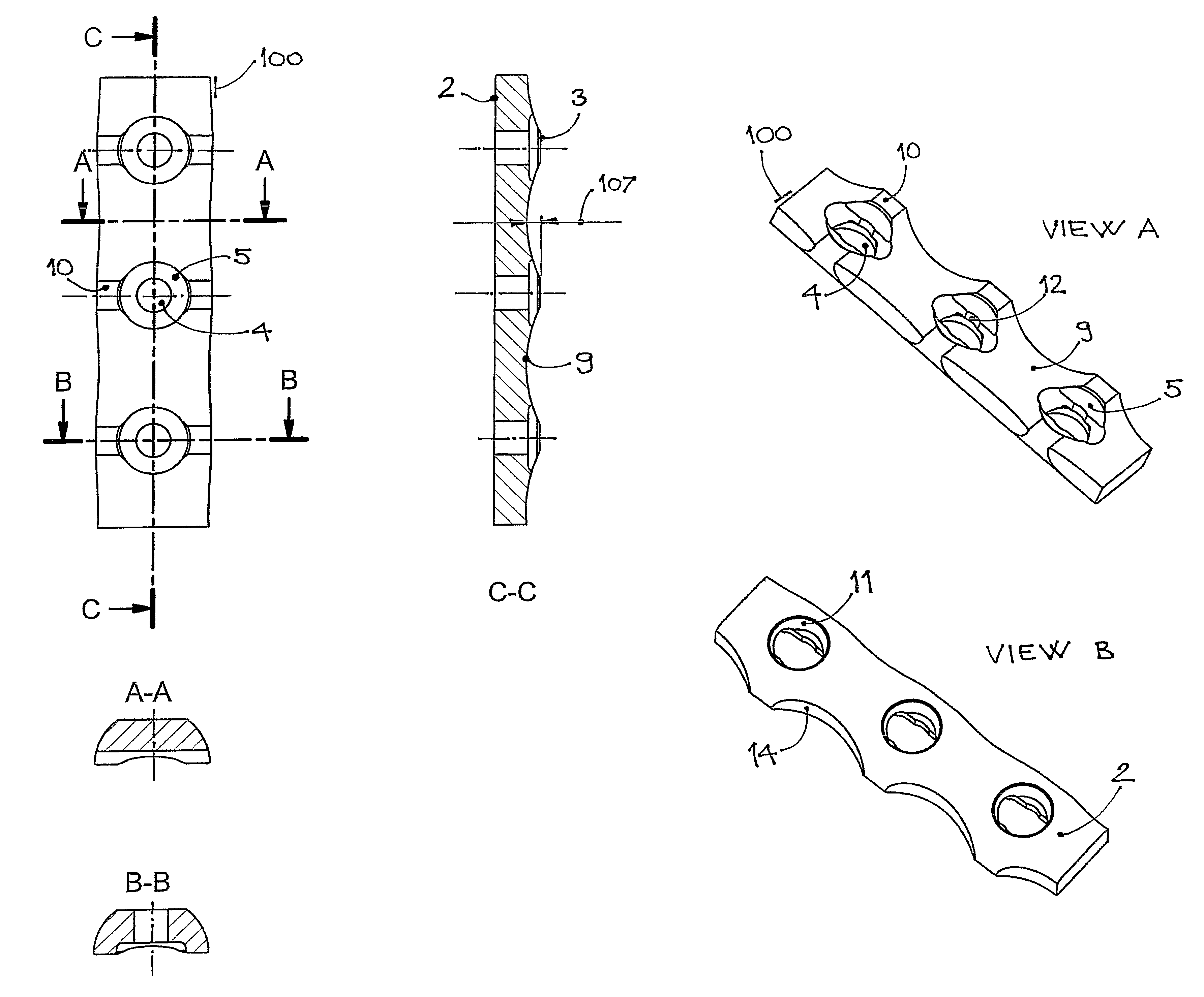
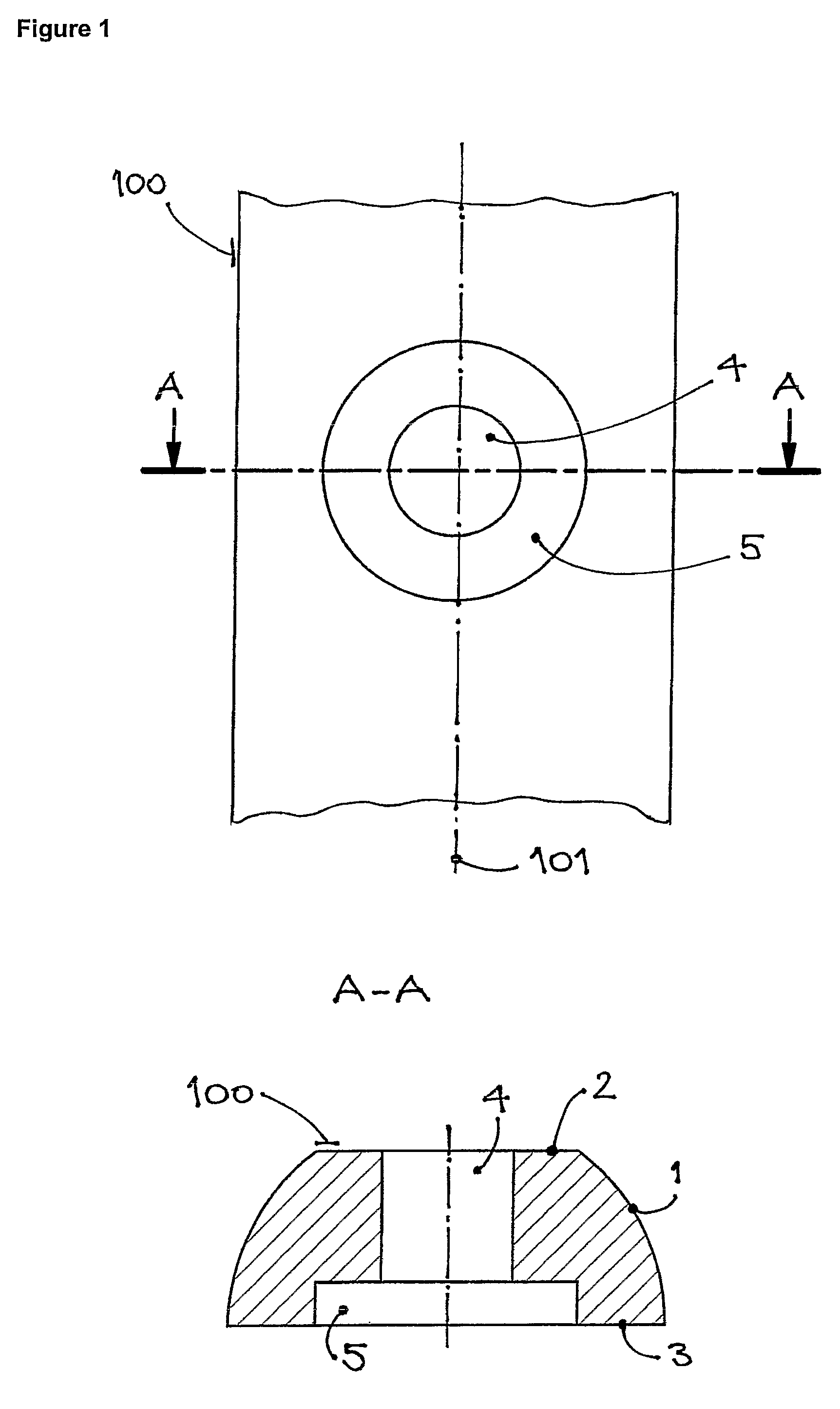
[0050]A section of the plate, 100, is shown in a normal projection from its lower, bone-facing surface, 3, on FIG. 1, together with a transverse cross section, A-A, cut through the screw hole, 4. The upper surface, 2, of the plate, 100, is parallel to the lower surface, 3, while the sides of the plate, 1, may be beneficially curved and inclined, so as to make the upper surface of the plate narrower in order to facilitate closure of the soft tissue over the plate. The screw hole, 4, is surrounded by a recess, 5, at the lower surface, 3, of the plate. The purpose of the recess, 5, is to eliminate the potential contact of the plate and the bone surrounding the screw. The lower surface, 3, of the plate, 100, is essentially planar.

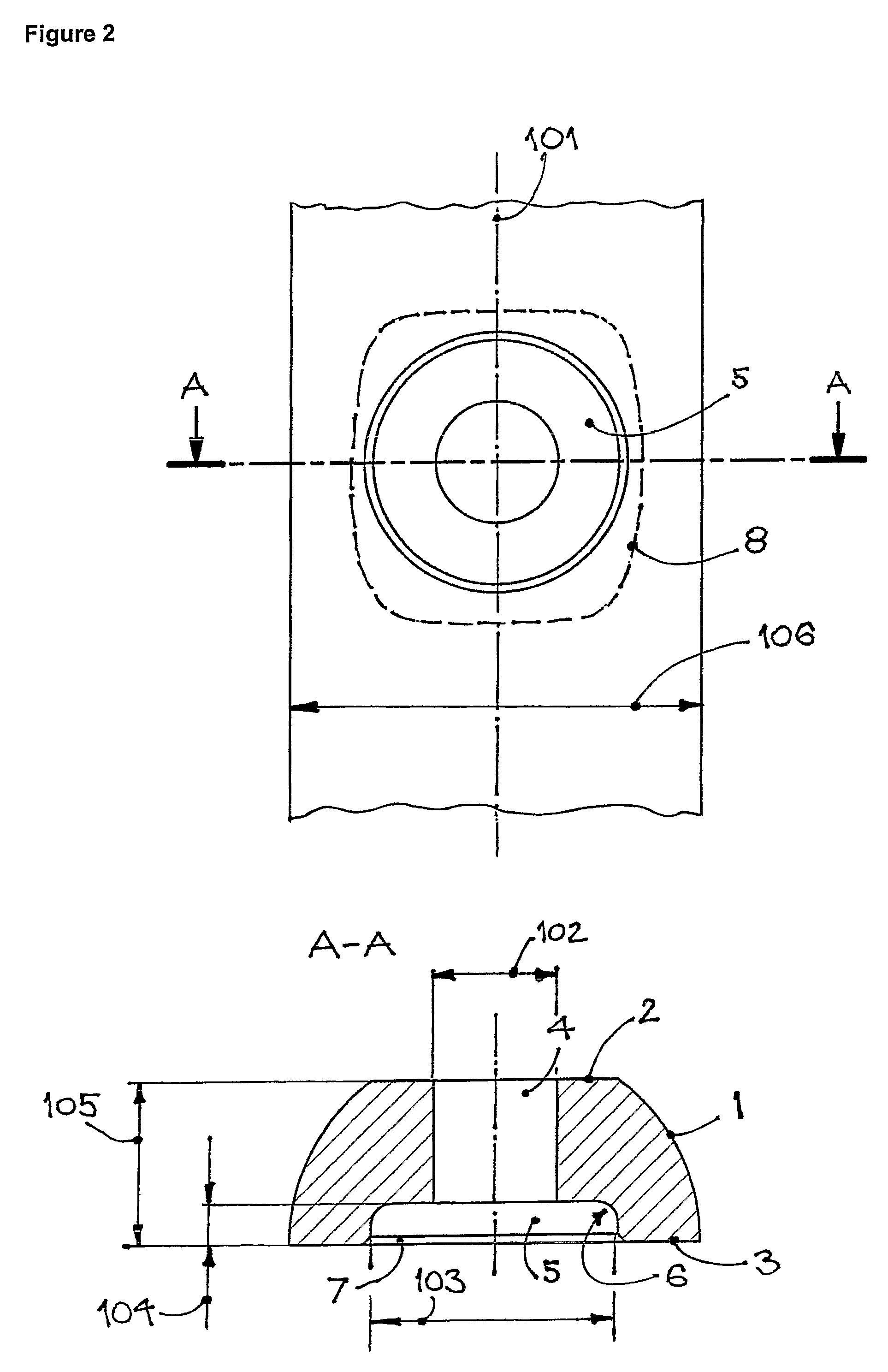
[0051]While the shape of the recess, 5, is shown as being circular in shape when viewed from the lower side of the plate, other shapes, such as that shown by dotted line, 8, on FIG. 2, can be used to achieve the same effect. A shape somewhat elongated in the di...


PUM


Abstract

A plate for treatment of bone fractures with reduced potential contact to bone through a combination of annular recesses surrounding the screw holes at the lower, bone facing surface of the plate and transverse grooves between the holes, allows for use of locking as well as conventional bone screws. With the transverse grooves cut into the plate from the lower side, as well as from the sides, the strength of the plate at the span between the holes is lower than at the screw holes. The plate can be bent in both planes without undue deformation of the screw holes. Protection of the holes during bending is afforded by hole plugs, which may be provided pre-installed in order to reduce surgery time. Screw hole plugs may then be left in place in the holes not used for bone screws.

Description

CROSS REFERENCE TO RELATED APPLICATION[0001]This application is a 35 USC §371 National Phase Entry Application from PCT / EP2006 / 001473, filed Feb. 17, 2006, and designating the United States.[0002]This invention relates to plates and screws for internal fixation of bone fractures. Geometry of the plate and in particular the lower, bone-facing, surface of the plate is at the core of the invention. It leads to a large reduction of the potential contact between the plate and the bone, hence minimizing the damage done to the bone vascular supply by plating itself. Furthermore, the plate screw holes are shaped to allow use of either conventional (ISO standardized) or the special, locking screws. These goals are achieved without compromising mechanical properties of the plate and the plate-bone construct.BACKGROUND[0003]Healing of fractured bones treated by internal fixation depends on blood supply, which is provided to bone by both endosteal and periosteal routes. Both can be damaged in t...

Claims


Application Information

Patent Timeline
Patent Type & Authority Patents(United States)
IPC IPC(8): A61B17/80A61B17/86
CPCA61B17/80A61B17/8085A61B17/8625
Inventor TEPIC, SLOBODAN
Owner KYON
Why Eureka
Try Eureka