Magnetic spring system for use in a resonant motor

a resonant motor and magnetic spring technology, applied in the field of magnetic spring systems for use in resonant motors, can solve the problems of reducing performance and eventual breakage, large number of stress cycles, metal fatigue in the springs,

Inactive Publication Date: 2015-03-03
KONINKLIJKE PHILIPS ELECTRONICS NV
View PDF21 Cites 12 Cited by
  • Summary
  • Abstract
  • Description
  • Claims
  • Application Information

AI Technical Summary

Problems solved by technology

However, after a large number of successive uses, the springs develop metal fatigue, resulting in reduced performance and eventual breakage.
The problem of metal fatigue in the springs is particularly prevalent in systems which operate at high frequency and hence have a large number of stress cycles.
In addition, metal springs have space limitations relative to a desired output stroke, since for a given degree of desired movement, i.e. 1 millimeter, for example, of a workpiece, approximately five times that distance is required between the opposing masses for the mechanical springs.

Method used


Image

  • Magnetic spring system for use in a resonant motor
  • Magnetic spring system for use in a resonant motor
  • Magnetic spring system for use in a resonant motor

Examples


Embodiment Construction

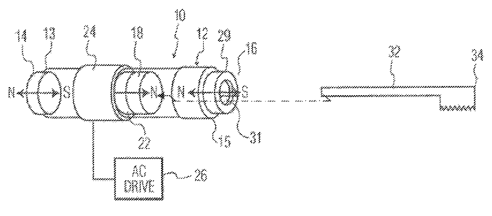
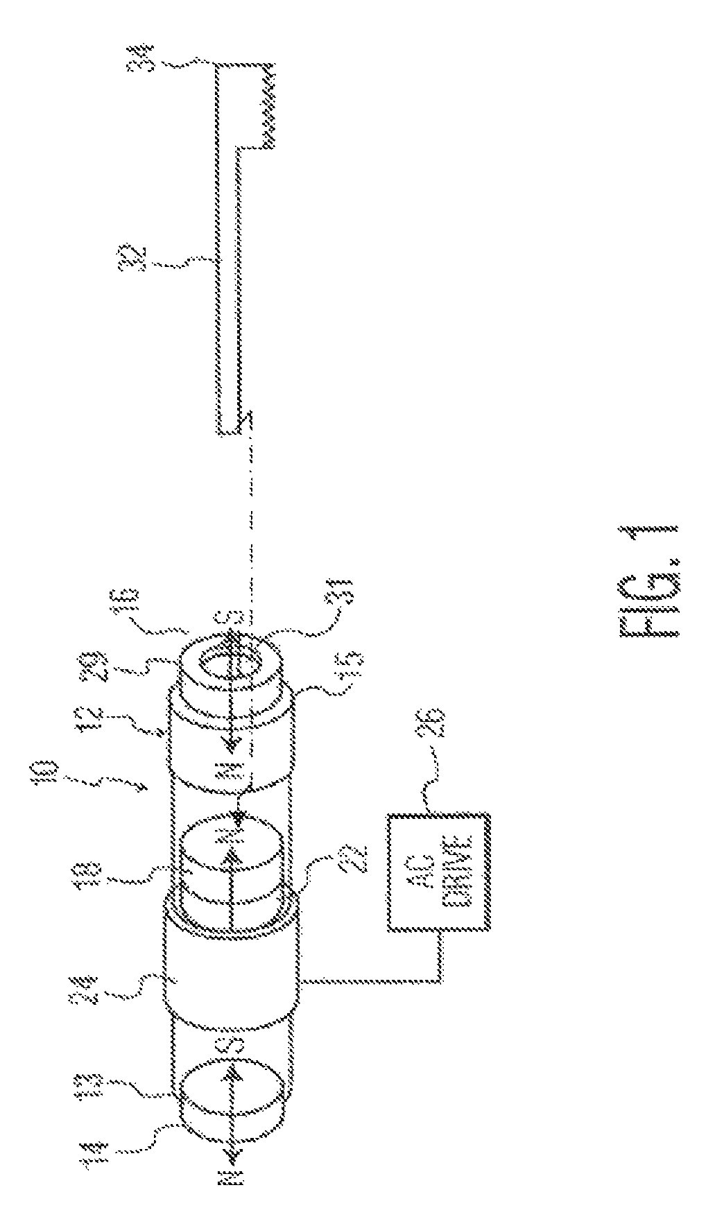
[0012]FIGS. 1 and 2 show a linear motor 10 which includes a magnetic action arrangement as an alternative to the conventional metal spring action to accomplish a linear output motion. The motor 10 includes a housing 12 which in the embodiment shown is in the form of a tube, although it could have other cross-sectional configurations. Fixedly mounted at the respective ends 13 and 15 of the housing are permanent magnets 14, 16, in the form of discs, having north and south polarity faces, as shown. One magnet 14 has its north polarity facing outward from end 13 of the housing, while the opposing magnet 16 has an opposing arrangement, i.e. the south polarity faces outwardly from end 15 of housing 12.

[0013]A third magnet 18 is positioned internally of the housing between magnets 14 and 16. The north polarity face of magnet 18 faces the north polarity of magnet 16 in a repelling action, while the south polarity face of magnet 18 faces the south polarity of magnet 14, also in a repelling m...


PUM


Abstract

A magnetic spring arrangement for a resonant motor including a housing, magnets fixed in position at opposing ends of the housing, a magnet positioned within the housing for movement toward and away from the fixed magnets in a reciprocal oscillating motion with a driving action produced by a stator coil and an AC drive signal, wherein an applicator member is attachable to the moving magnet for corresponding movement of a workpiece portion of the applicator member.

Description

TECHNICAL FIELD[0001]This invention relates generally to resonant motors which produce an oscillating output action, and more particularly concerns such a motor using magnetic action as an alternative to conventional springs.BACKGROUND OF THE INVENTION[0002]In resonant motors which produce an oscillating output action, metal springs are part of the motor contributing to the action. However, after a large number of successive uses, the springs develop metal fatigue, resulting in reduced performance and eventual breakage. The problem of metal fatigue in the springs is particularly prevalent in systems which operate at high frequency and hence have a large number of stress cycles. In addition, metal springs have space limitations relative to a desired output stroke, since for a given degree of desired movement, i.e. 1 millimeter, for example, of a workpiece, approximately five times that distance is required between the opposing masses for the mechanical springs.[0003]It would hence be...

Claims


Application Information

Patent Timeline
Patent Type & Authority Patents(United States)
IPC IPC(8): H02K33/00A46B13/00A61C17/22F16F6/00H02K33/06
CPCF16F6/005A61C17/221H02K33/06A61C17/34F16F6/00H02K35/00A61C17/3445H02K33/16
Inventor HEADSTROM, PATRICK
Owner KONINKLIJKE PHILIPS ELECTRONICS NV
Why Eureka
Try Eureka