Delaying startup under fault conditions

a technology of led lamp controller and fault condition, which is applied in the direction of electric variable regulation, process and machine control, instruments, etc., can solve the problems of limited fault detection circuits in conventional led controllers, high power consumption in led lamps, and thermal stress on led lamp circuitry

Active Publication Date: 2015-03-03
DIALOG SEMICONDUCTOR INC
View PDF15 Cites 7 Cited by
  • Summary
  • Abstract
  • Description
  • Claims
  • Application Information

AI Technical Summary

Benefits of technology

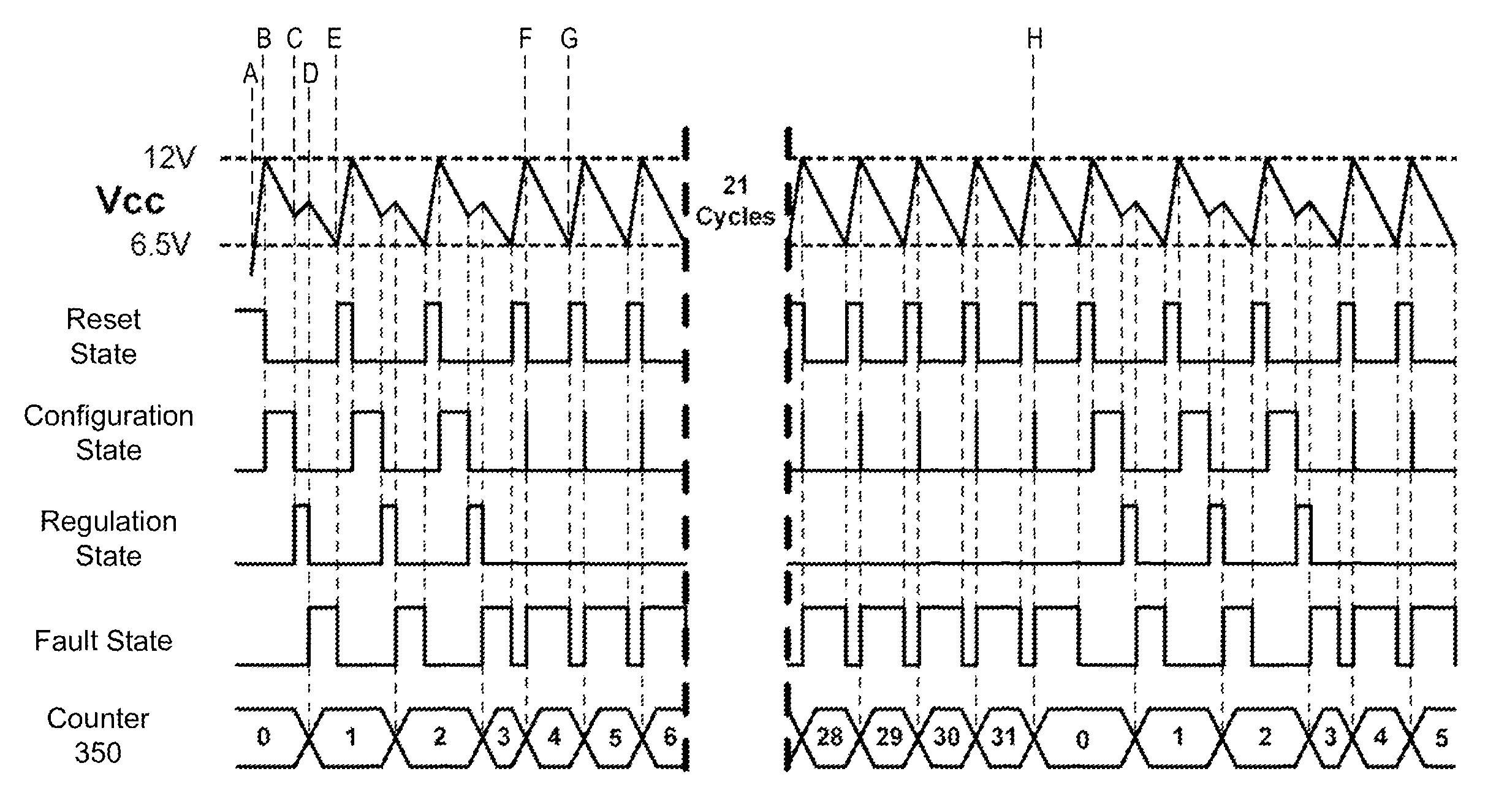
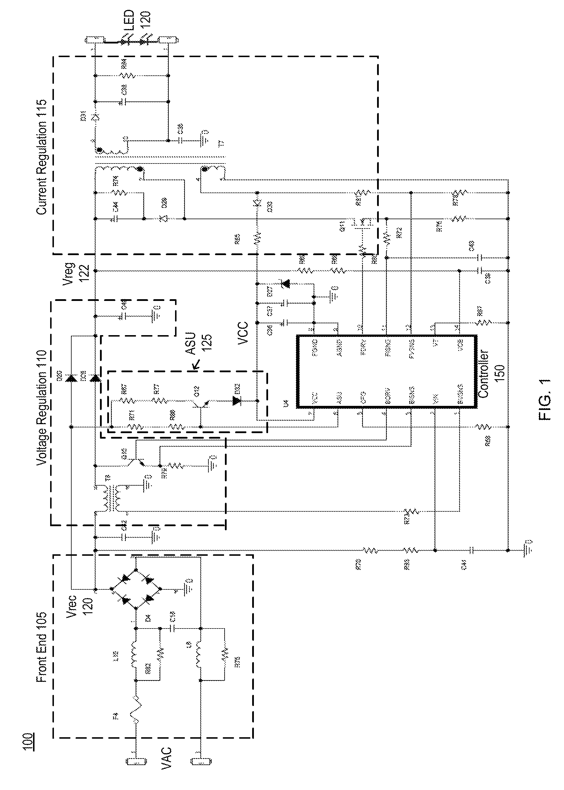
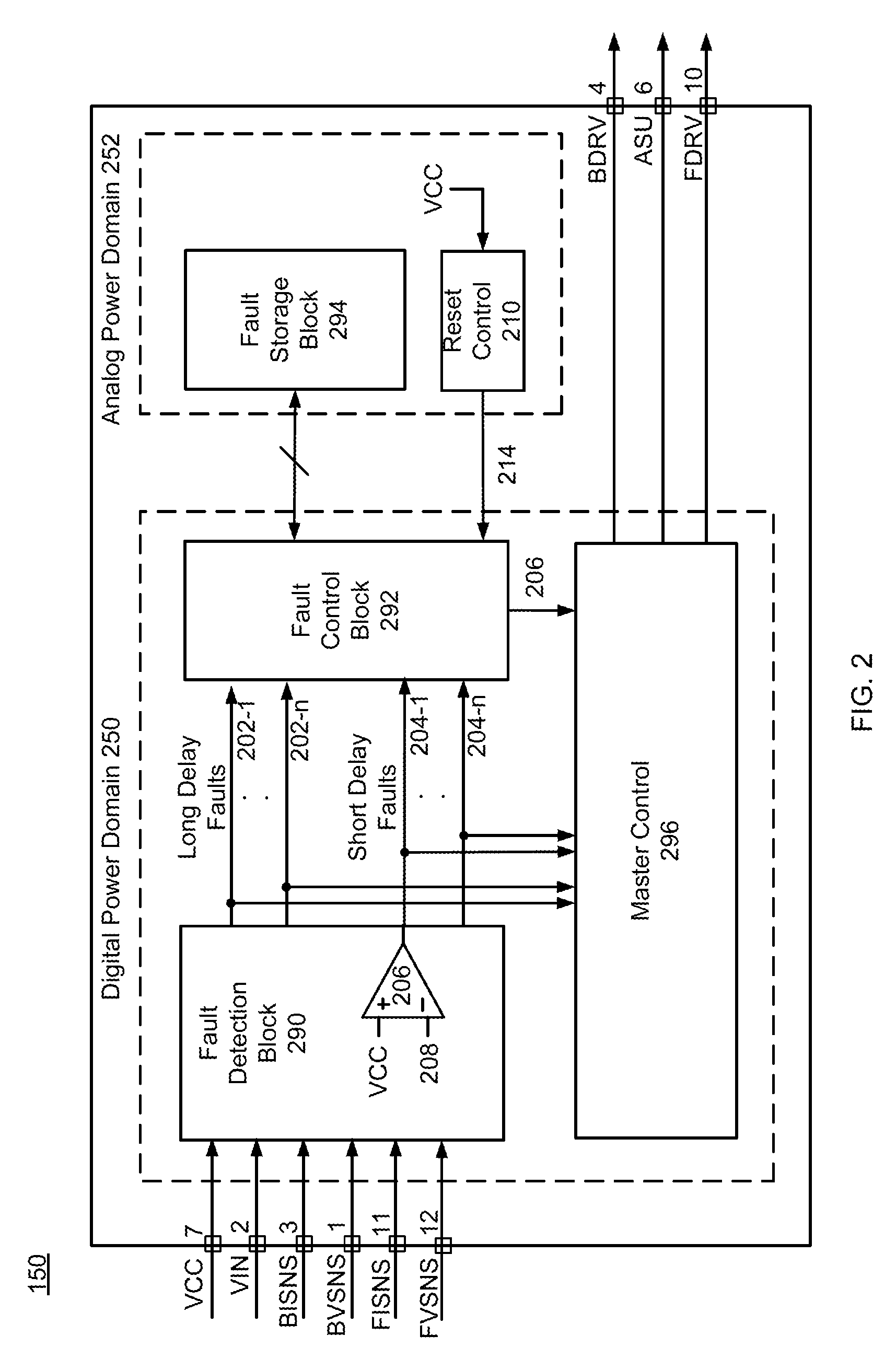
[0009]During a first power cycle, a fault condition occurs in the LED lamp and the LED lamp controller detects the type of the fault condition. During second power cycles that are subsequent to the first power cycle, the LED lamp controller is configured to prevent completion of the configuration state (e.g., by preventing the configuration state from starting or by discontinuing the configuration state after it starts). The LED lamp controller is also configured to control a number of the second power cycles during which the completion of the configuration state is prevented based on the type of the detected fault condition. The LED controller thus varies a delay between when a fault condition is detected and when the LED controller is permitted to start up properly according to the type of fault condition that is detected.

Problems solved by technology

A high amount of power consumption in the LED lamp can occur during the time that the controller is in the configuration state due to the way in which the controller is driving the circuitry of the LED lamp.
Repeated power cycles cause thermal stress on circuitry in the LED lamp if the amount of time spent in the configuration states is too long.
However, conventional LED lamp controllers are fairly simplistic and use a one-size fits all approach that treats all fault conditions in the same manner, regardless of the severity of the fault.
In addition, fault detection circuits in conventional LED controllers are limited in the types of faults that they can detect.

Method used


Image

  • Delaying startup under fault conditions
  • Delaying startup under fault conditions
  • Delaying startup under fault conditions

Examples


Embodiment Construction

[0020]The Figures (FIG.) and the following description relate to preferred embodiments of the present disclosure by way of illustration only. It should be noted that from the following discussion, alternative embodiments of the structures and methods disclosed herein will be readily recognized as viable alternatives that may be employed without departing from the principles of the present disclosure.

[0021]Reference will now be made in detail to several embodiments of the present disclosure(s), examples of which are illustrated in the accompanying figures. It is noted that wherever practicable similar or like reference numbers may be used in the figures and may indicate similar or like functionality. The figures depict embodiments of the present disclosure for purposes of illustration only. One skilled in the art will readily recognize from the following description that alternative embodiments of the structures and methods illustrated herein may be employed without departing from th...


PUM


Abstract

A LED lamp that includes a LED lamp controller with delayed startup after a fault condition is detected. The type of the fault condition is used in determining a length of the startup delay, such as a number of power cycles during which the LED lamp controller is prevented from completing its configuration. Examples of different types of fault conditions include faults in a supply voltage or faults in a feedback voltage to the LED lamp controller. Fault type information can also be stored in circuitry that retains data and is not reset across the power cycles.

Description

CROSS REFERENCE TO RELATED APPLICATION[0001]This application claims priority from U.S. Provisional Patent Application No. 61 / 616,749, filed on Mar. 28, 2012, the contents of which are incorporated by reference herein in their entirety.BACKGROUND[0002]1. Field of the Disclosure[0003]The present disclosure relates to a light emitting diode (LED) lamp controller, and more specifically to a LED lamp controller with delayed startup under fault conditions.[0004]2. Description of the Related Arts[0005]A controller circuit for a LED lamp must detect and respond appropriately to many potential fault conditions. Generally, when a fault is detected, the controller circuit stops driving its output pins and enters a shutdown state to prevent any further damage from occurring. After some amount of time, the controller restarts and the LED lamp will be powered up if the fault condition has been removed. During each restart, the controller enters a configuration state during which the internal para...

Claims


Application Information

Patent Timeline
Patent Type & Authority Patents(United States)
IPC IPC(8): H05B37/00H05B37/03H05B44/00
CPCH05B37/038H05B33/0815H05B33/0887Y02B20/347H05B45/50Y02B20/30H05B45/38H05B45/385H05B45/10H05B47/235H05B45/37
Inventor MYERS, RICHARD M.POON, CLARITA C.YAN, LIANG
Owner DIALOG SEMICONDUCTOR INC
Why Eureka
Try Eureka