Liquid level sensor having a virtual ring

a liquid level sensor and virtual ring technology, applied in liquid/fluent solid measurement, instruments, machines/engines, etc., can solve the problems of high manufacturing cost of sensor types, limited use of containment, and unclear how this can inhibit or stop the formation of residues

Inactive Publication Date: 2006-12-05
STANDEX INT CORP
View PDF3 Cites 2 Cited by
  • Summary
  • Abstract
  • Description
  • Claims
  • Application Information

AI Technical Summary

Benefits of technology

[0011]It is an aspect of the invention to provide a liquid level sensor that prevents false “full” indications due to the buildup of residue on the inside of the container.
[0012]It is another aspect of the invention to provide a liquid level sensor that provides a virtual bias ring that is electrically charged the same polarity as the tip of the probe of the sensor so as to prevent a current path being established between probe tip and ground via any residue buildup on the probe or by the highly conductive nature of the liquid itself inside of the container.
[0015]It is still another aspect of the invention to provide a liquid level sensor that can be inexpensively manufactured.
[0019]The invention is a liquid level sensor apparatus for determining the level of a conductive liquid held within a container having inside walls, one of which is an attachment wall, wherein the container is subject to the accumulation of residue as a consequence of the liquid contained therein. A housing which is attached to attachment wall of the container is provided. An insulated probe having an attachment end and a sensor end is also provided, wherein the attachment end of said insulated probe is connected to said housing such that the probe end is able to contact the conductive liquid held therein. A conducting sensor tip having a voltage is disposed at the probe end of said insulated probe. A ground connection having an electrical polarity, said ground connection is in contact with the conductive liquid. An exposed tip of a bias wire exits from said insulated probe positioned between said attachment end and said sensor end. A bias voltage at said exposed tip provides a virtual bias voltage circumferential ring around said insulated probe immediately adjacent to said exposed tip. The bias voltage of the virtual bias voltage circumferential ring has a polarity opposite of said ground connection wherein the bias voltage corresponds to the voltage of said conducting sensor tip. Once the liquid is in contact with said conducting sensor tip at a predetermined level, a circuit is completed to said ground connection which indicates a “full” condition. If the liquid is not in contact with said conducting sensor tip at the predetermined level, a “not full” condition is indicated. The bias voltage of said virtual circumferential ring prevents a false indication of a “full” condition by preventing the completion of the circuit from said conducting sensor tip to said ground connection via residue on the container walls and said insulated probe even when the liquid is not in contact with said conducting sensor tip.

Problems solved by technology

While Todd does suggest that by having his encapsulator with open upper and lower ends provides for self-flushing of debris, it is unclear how this can inhibit or stop the problems associated with residue formation, particularly as found in older systems.
While this device solves the corrosive problem found in processing industries using materials in liquid form, its use is limited to containment vessels which have sufficient outside room to put the sensor in place.
Further, this type of sensor is expensive to manufacture in that it must be shaped to correspond to the particular shape of the vessel being used.
Also, the thickness and material used for the vessel can also appreciably impact the accuracy and sensitivity of the device.
Thus, many commonly used containers are unsuitable for use with this device without having substantial additional expense.
While this device is simple and inexpensive to build, no protection against false “full” readings due to the accumulation of conductive sludge or other residue is disclosed or suggested.
Further, their device is quite complicated and expensive requiring the use of alternating current, an oscillator, and filters as well as other circuitry in order to achieve their objectives.

Method used


Image

  • Liquid level sensor having a virtual ring
  • Liquid level sensor having a virtual ring
  • Liquid level sensor having a virtual ring

Examples


Embodiment Construction

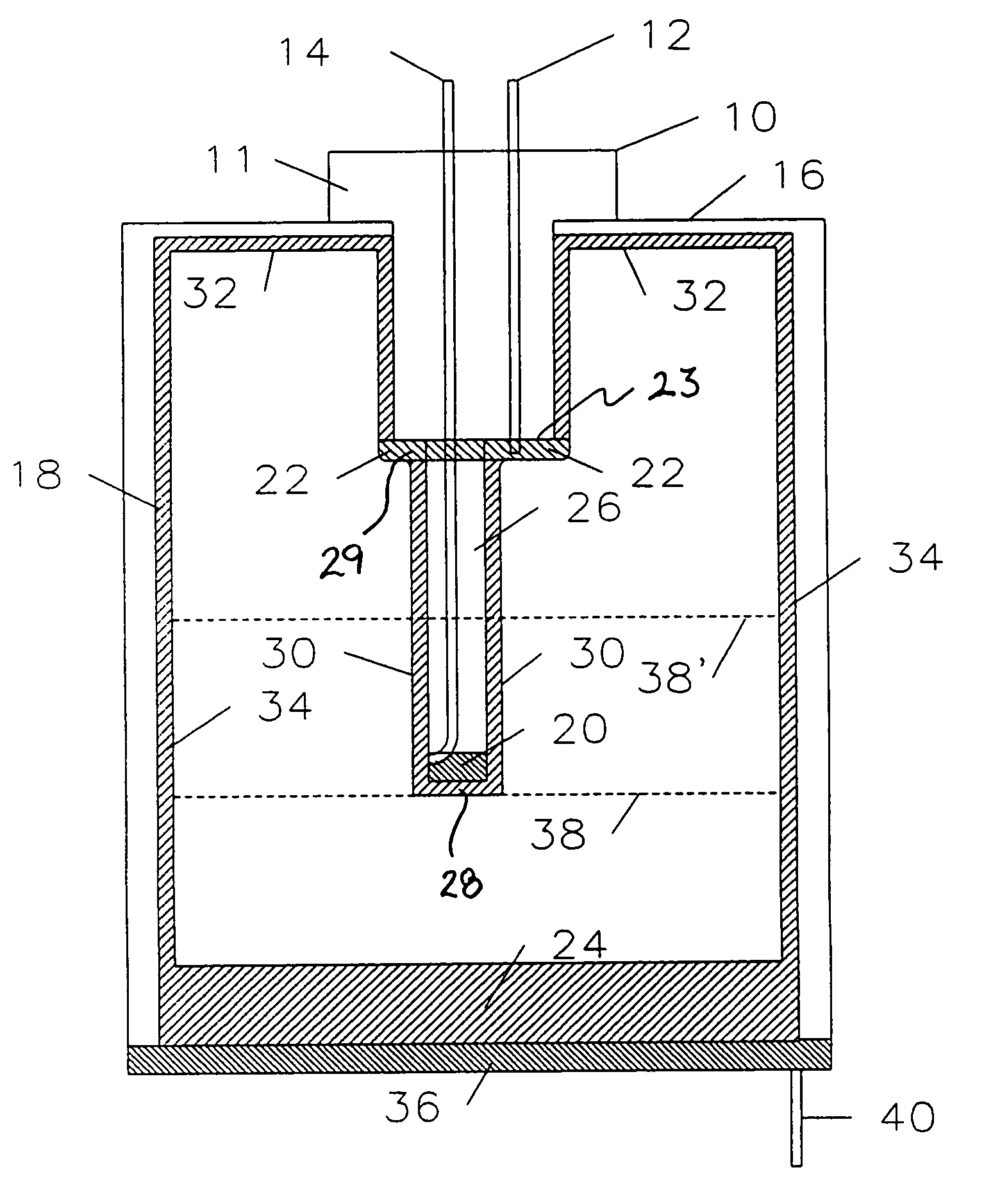
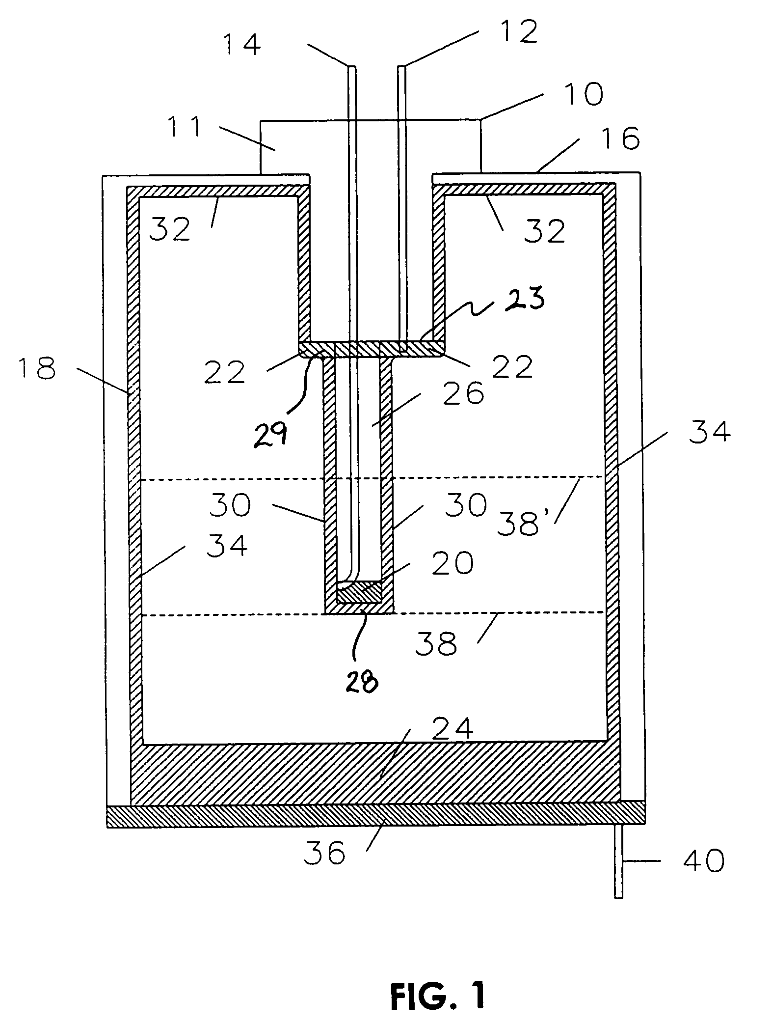
[0022]Referring first to FIG. 1, an illustration of the sensor 10 is shown. The invention is a liquid level sensor that prevents a false “full” reading due to the build-up of conductive residue 18. Residue 18 usually consists primarily of the highly conductive liquid 24 that fails to drain from the inside of tank 16. In this case, liquid 24 is typically dishwasher soap or hard water that may be encountered in sump pump applications. This type of situation typically worsens in aging systems due to fluid contamination by metals and salts in the system.

[0023]Tank 16 holds liquid 24 which must be maintained below or at a predetermined level 38. As noted above, many elaborate schemes have been developed to determine when liquid 24 is less than level 38. However, the least expensive of these is a simple conductive circuit having a sensor that causes a light or other indicator well known in the art to be either activated or deactivated once the liquid level is below or at level 38.

[0024]As...


PUM


Abstract

A liquid level sensor for conductive liquids having a virtual bias ring to prevent false “full” indications. The sensor is an inexpensive conductive probe that can be installed in any tank or container used to contain a conductive liquid. The build up of residue such as conductive fluid that fails to drain on the inside of the container wall and probe pieces can cause a short between the probe and ground. This situation will result in falsely showing that the level of the liquid being measured is at least at the minimum predetermined requirement even though the actual level may be far less than that amount. The bias ring is a virtual “ring” that is provided around the insulating base of the sensing probe between the probe tip and the top inside of the tank. The probe is then given a charge (positive for negative ground systems) which interrupts the current path between the sensing tip of the probe and ground via the conducting residue. Consequently, the sensor will read correctly despite the conductive residue that may be present.

Description

[0001]This application is a continuation-in-part of U.S. patent application Ser. No. 10 / 410,836, filed Apr. 10, 2003 now U.S. Pat. No. 6,727,822, which is a continuation-in-part of U.S. patent application Ser. No. 10 / 184,010, filed Jun. 27, 2002, now issued as U.S. Pat. No. 6,624,755 on Sep. 23, 2003.FIELD OF THE INVENTION[0002]This invention relates to a liquid level sensor, in particular, the use of a conductance measuring sensor to determine the level of a conductive liquid contained within a vessel.BACKGROUND OF THE INVENTION[0003]The use of devices to indicate the level of liquid within a tank or container is well known in the art. The need for knowing whether a liquid in a container is above or below a predetermined level is found in many very different situations. Typical of those situations where the liquid level must not be permitted to fall below a predetermined level are found in automobile radiators, windshield washer containers or oil in an engine crankcase. The situati...

Claims


Application Information

Patent Timeline
Patent Type & Authority Patents(United States)
IPC IPC(8): G08B21/00G01F23/24G01F23/68
CPCG01F23/242G01F23/243G01F23/683
Inventor CHAMBERLIN, EDWARD R.
Owner STANDEX INT CORP
Why Eureka
Try Eureka