
Replacement of a faulty memory cell with a spare cell for a memory circuit

a memory circuit and memory cell technology, applied in the field of solid-state memory techniques, can solve the problems of reducing the size of the access transistor and the storage capacitor, affecting the performance of the memory circuit, and relative longer latency memories, so as to facilitate the repair and improve memory performance. the effect of performance and lifetim

Active Publication Date: 2015-03-03
RAMBUS INC
View PDF4 Cites 2 Cited by
  • Summary
  • Abstract
  • Description
  • Claims
  • Application Information

AI Technical Summary

Benefits of technology

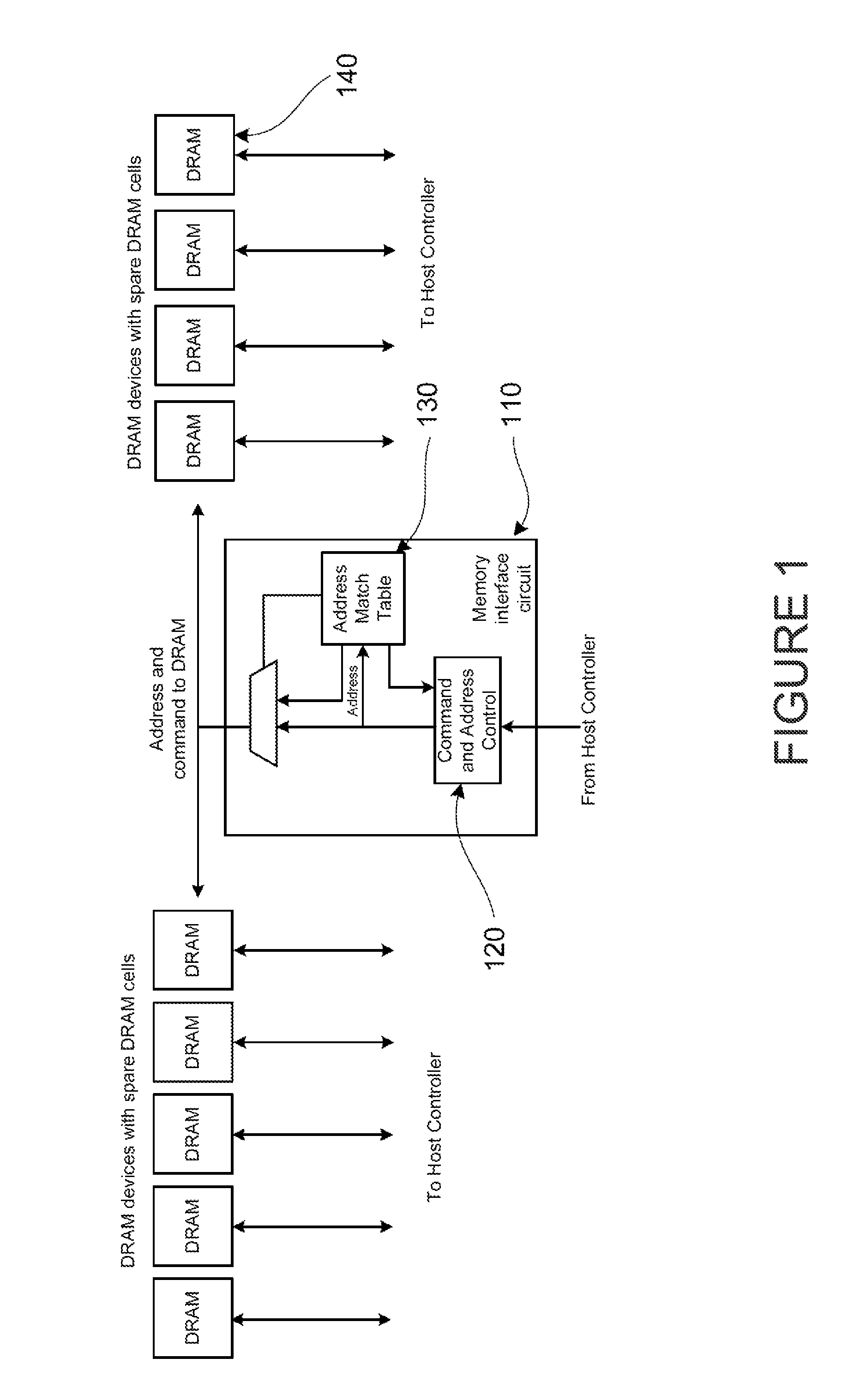
[0018]Many benefits are achieved by way of the present invention over conventional embodiments and techniques. For example, embodiments of a memory IC device can have improved performance and lifetime. Embodiments of a memory interface device can facilitate the “repair” of bad or faulty memory cells, or even undesirable memory cells due to aging, deterioration, or the like. Spare memory cells from a memory IC device can be rerouted via a memory interface device upon detection of predetermined characteristics of memory cell to be replaced. These implementations provide several means of maintaining or improving memory performance, which can be tailored depending on various hardware and / or software requirements of specific applications.

Problems solved by technology

Additionally, such classes also include relatively longer latency memories that do not have infinite endurance or usage cycles, and may degrade with respect to age or repeated accesses.
This necessarily results in a reduction in the sizes of the access transistor and storage capacitor, which can lead to several limitations.
This leakage characteristic—and thus each cell's data retention time—varies from transistor to transistor; however, this variability increases as the size of the access transistors is reduced.
Another problem is that a shrinking memory cell results in a smaller storage capacitor, and thus a reduced storage capacitance.
This can also adversely affect the data retention time characteristics of the cells.

Method used


Image

  • Replacement of a faulty memory cell with a spare cell for a memory circuit
  • Replacement of a faulty memory cell with a spare cell for a memory circuit
  • Replacement of a faulty memory cell with a spare cell for a memory circuit

Examples


Embodiment Construction

[0028]A trend in the development of memory storage devices is that as the storage cells continue to shrink due to advancements in process technology, storage cells in low latency memories such as DRAM devices may become more susceptible to errors that occur due to aging effects or repeated accesses. Moreover, the number of weak bits due to natural process variations will continue to increase. Accordingly, it is desirable that spare storage cells can be utilized to correct for the presence of faulty storage cells in low latency memory that may develop over the lifetime of the device.

[0029]The present invention is related to memory devices for electronic applications. More specifically, embodiments of the present invention provide memory interface devices and memory IC (integrated circuit) devices, which can be implemented various computing devices, servers, and the like. Merely by way of example, these devices can be configured for or implemented as memory devices, such as SDRAM, DDR...


PUM


Abstract

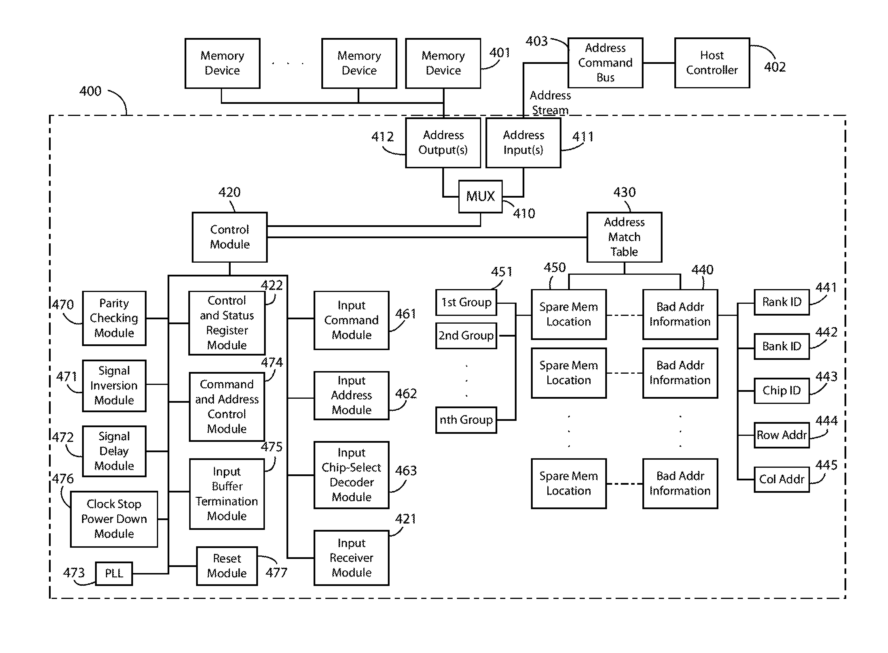
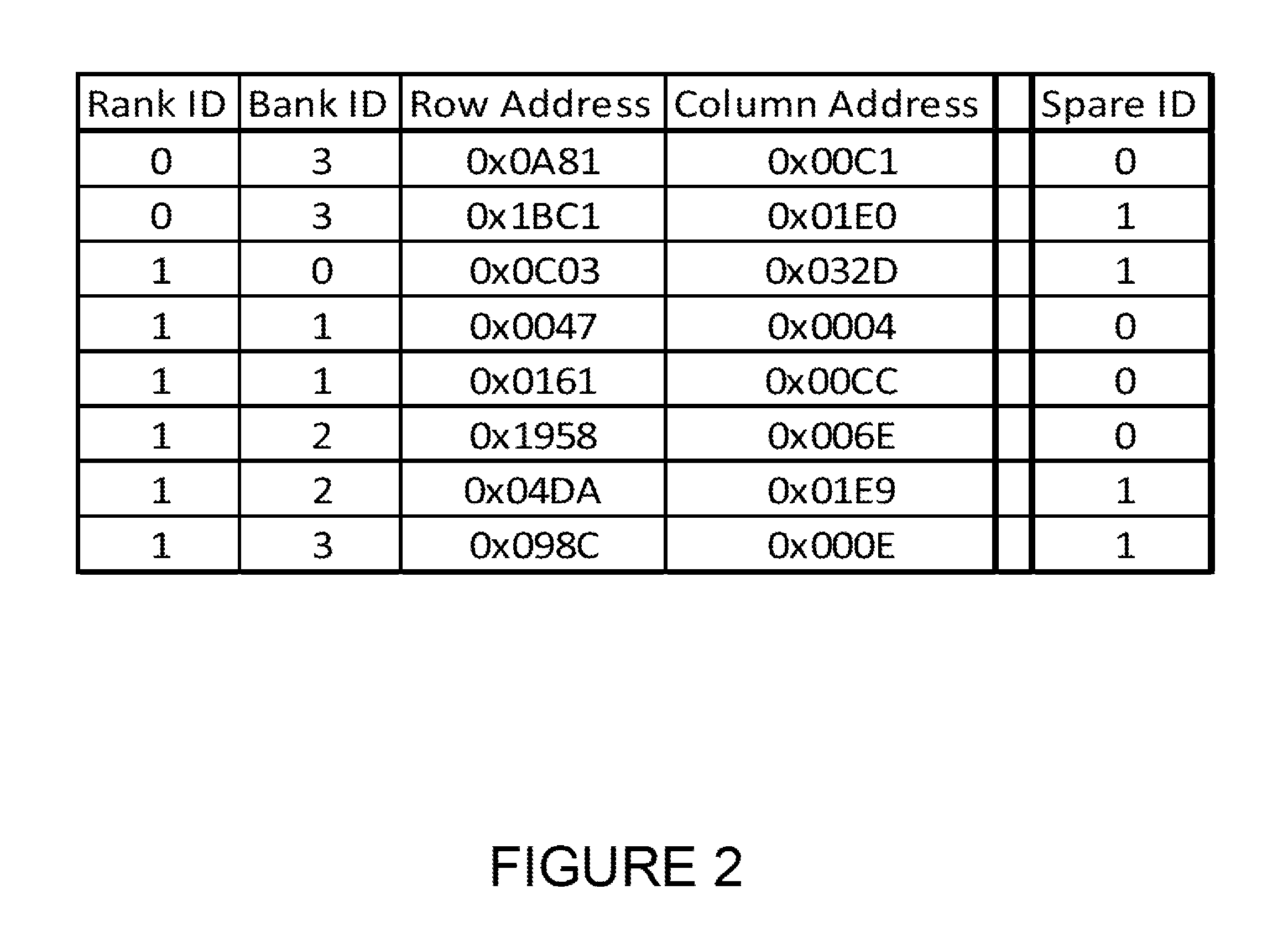
A memory interface device has an address input(s) configured to receive address information from an address stream of a host controller; an address output(s) configured to drive address information, and is coupled to a plurality of memory devices; an address match table comprising at least a revised address corresponding to a spare memory location; a control module configured to determine address information from an address stream from an address command bus coupled to a host controller during a run time operation; and a multiplexer coupled to the address input and coupled to the address output.

Description

CROSS-REFERENCES TO RELATED APPLICATIONS[0001]The present application is a continuation-in part application of and incorporates by reference, for all purposes, each of the following patent application: U.S. patent application Ser. No. 13 / 620,288 filed Sep. 14, 2012, which claims priority to U.S. Provisional Application No. 61 / 535,780 filed Sep. 16, 2011.BACKGROUND OF THE DISCLOSURE[0002]The present invention relates generally to solid state memory techniques. More particularly, the present invention provides methods and devices for repairing a “bad memory cell” with a substitute cell for a memory device such as a dynamic random access memory (“DRAM”) device or others.[0003]In memory systems, two general classes of memories exist. Such classes include low latency memories. The low latency memories have effectively infinite endurance or usage-cycles and do not degrade with respect to age or repeated accesses. Additionally, such classes also include relatively longer latency memories t...

Claims


Application Information

Patent Timeline
Patent Type & Authority Patents(United States)
IPC IPC(8): G11C29/04G11C11/24G11C7/10G11C11/408G11C11/4093G11C29/00
CPCG11C29/04G11C11/24G11C29/808G11C7/1012G11C11/4093G11C29/846G11C11/408
Inventor WANG, DAVID T.
Owner RAMBUS INC
Learn More