
By-products (impurity) removal

a technology of impurities and by-products, applied in the field of electrolysis, can solve the problems of decreasing performance upon use, and none of these documents deal with the removal of non-gaseous by-products or contaminants, and achieve the effect of improving performance and life, and longer intervals

Active Publication Date: 2022-01-27
SEDO ENG SA
View PDF0 Cites 0 Cited by
  • Summary
  • Abstract
  • Description
  • Claims
  • Application Information

AI Technical Summary

Benefits of technology

The invention is about a better electrolytic reactor that can make dyes more efficiently and last longer. It needs to be cleaned less often and makes purer dyes.

Problems solved by technology

While electrolysis is a clean method since it involves less chemicals than other reduction methods, it suffers from decreasing performance upon use, at least in part due to electrode contamination.
None of these documents deals with the removal of non-gaseous by-products or contaminants from a solution comprising non-gaseous products.

Method used


Image

  • By-products (impurity) removal
  • By-products (impurity) removal
  • By-products (impurity) removal

Examples


Embodiment Construction

[0062]The method will now be further illustrated for a dye reduction method, in particular an indigo reduction method.

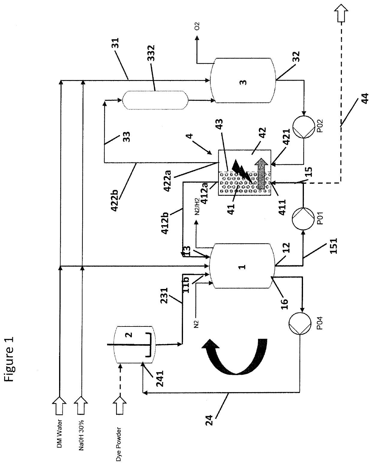
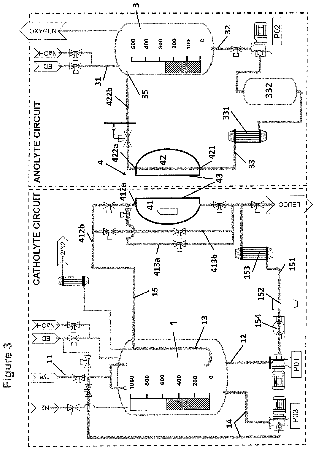
[0063]FIG. 1 shows the basic equipment of an anolyte circuit with an electrolytic cell 4 comprising a cathode compartment 41 and an anode compartment 42 separated from each other by a separator 43, in particular a semipermeable membrane. The anolyte vessel 3 is fed with electrolyte, in particular caustic soda via anolyte supply pipe 31. From anolyte vessel 3 the anolyte is fed to the anode compartment 42 via anolyte outlet 32 into anolyte circulation loop or anolyte circulation pipe 33, respectively equipped with a anolyte circulation pump P02. The anolyte enters the anode compartment via anolyte inlet 421, passes through the anode compartment 42 and is returned from the anode compartment 42 via anolyte outlet 422a and anolyte return pipe 422b into the anolyte vessel 3. Also provided within the anolyte circulation loop is an adsorption filter 332 that can be placed a...


PUM


Abstract

An electrolytic reactor comprises at least one electrolytic cell with an anode compartment and a cathode compartment separated by a separator, in particular a semipermeable membrane. The anode compartment comprises an inlet and an outlet for anolyte at opposed ends, said inlet and outlet being connected with each other via an anolyte circulation pipe equipped with a storage means for anolyte, an anolyte vessel and at least one adsorption filter for adsorbing molecular impurities. When molecular impurities comes from the cathode compartment through the separator, the electrolytic reactor acts also as a cleaning device for the catholyte.

Description

TECHNICAL FIELD[0001]The disclosure pertains to the field of electrolysis with flown through cells suitable for the reduction of vat dyes like indigo and sulfur dyes.BACKGROUND ART[0002]Reduction of vat dyes and sulfur dyes by means of electrolysis is already known (see e.g. WO 2007 / 147283 A2). While electrolysis is a clean method since it involves less chemicals than other reduction methods, it suffers from decreasing performance upon use, at least in part due to electrode contamination.[0003]DE 10 2015 202 117 A1 discloses an electrochemical method for converting carbon dioxide into carbon monoxide, methane or ethene. Undesired by-products are formiates that can deposit onto the electrode surface. These by-products are generated in the cathode compartment and removed therefrom by means of a filter positioned downstream of a gas separation.[0004]U.S. Pat. No. 3,701,719 A discloses the electrochemical production of olefin oxides from olefins via a halohydrin intermediate. Both the a...

Claims


Application Information

Patent Timeline
IPC IPC(8): C25B15/08C25B9/19C25B3/25C25B3/05C25B13/02C25B13/05C25B9/70
CPCC25B15/085C25B9/19C25B3/25C25B9/70C25B13/02C25B13/05C25B3/05C25B15/08C25B9/40
Inventor CRETTENAND, DAVIDCHAPPOT, GRÉGOIRECHAPPOT, LUDOVICGÜBELI, HERBERT
Owner SEDO ENG SA
Learn More