
Wheel for vehicles

Inactive Publication Date: 2015-03-10
PIRELLI TYRE SPA
View PDF17 Cites 3 Cited by
  • Summary
  • Abstract
  • Description
  • Claims
  • Application Information

AI Technical Summary

Benefits of technology

The patent describes a mechanical coupling element that helps prevent the movement of the tire in relation to the rim when the tire is inflated. This element ensures a good air seal and prevents incorrect mounting of the parts that affect the seal. Overall, this invention improves the stability and efficiency of the inflated tire.

Problems solved by technology

The Applicant has also observed that the use on tyre and rim of complementary knurls oriented along the axial direction is not very practical from the mounting standpoint, due to the difficulties of precisely engaging the knurls with each other.
The applicant also observed that the rubber which constitutes the tyre can be deformed during mounting, so that it is possible that a defective engagement between the knurls can allow an air escape along the axial direction, with a consequent and totally undesired pressure loss phenomenon over time.
Finally, the Applicant verified that the knurled configuration provided on at least part of the outer surface of the beads is difficult to obtain in a precise manner during the moulding and vulcanization operations of the tyre, with a possible worsening of the problems related to a poor air seal connected to a defective engagement with the complementary knurls formed in the rim.

Method used


Image

  • Wheel for vehicles
  • Wheel for vehicles
  • Wheel for vehicles

Examples


first embodiment

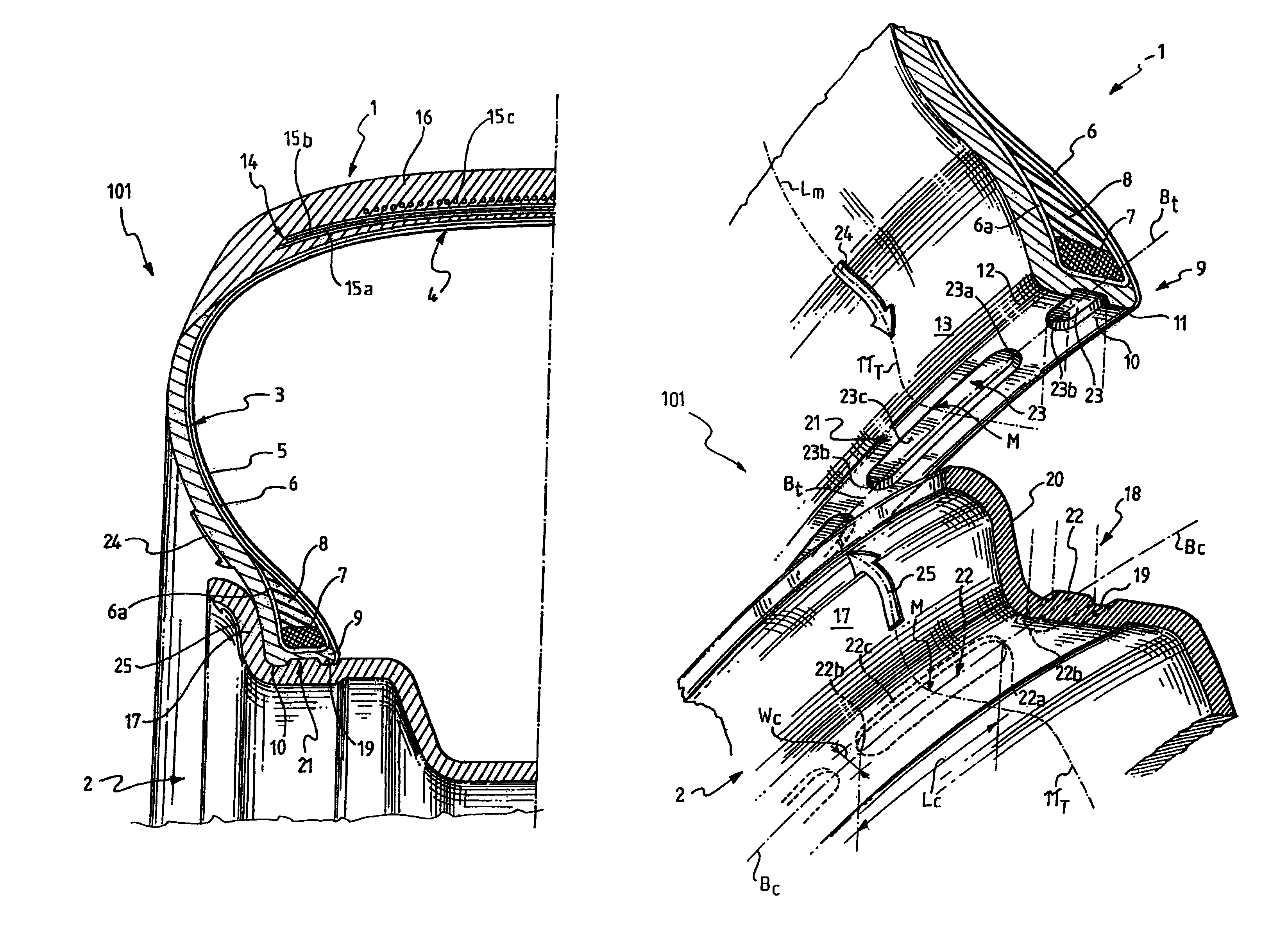
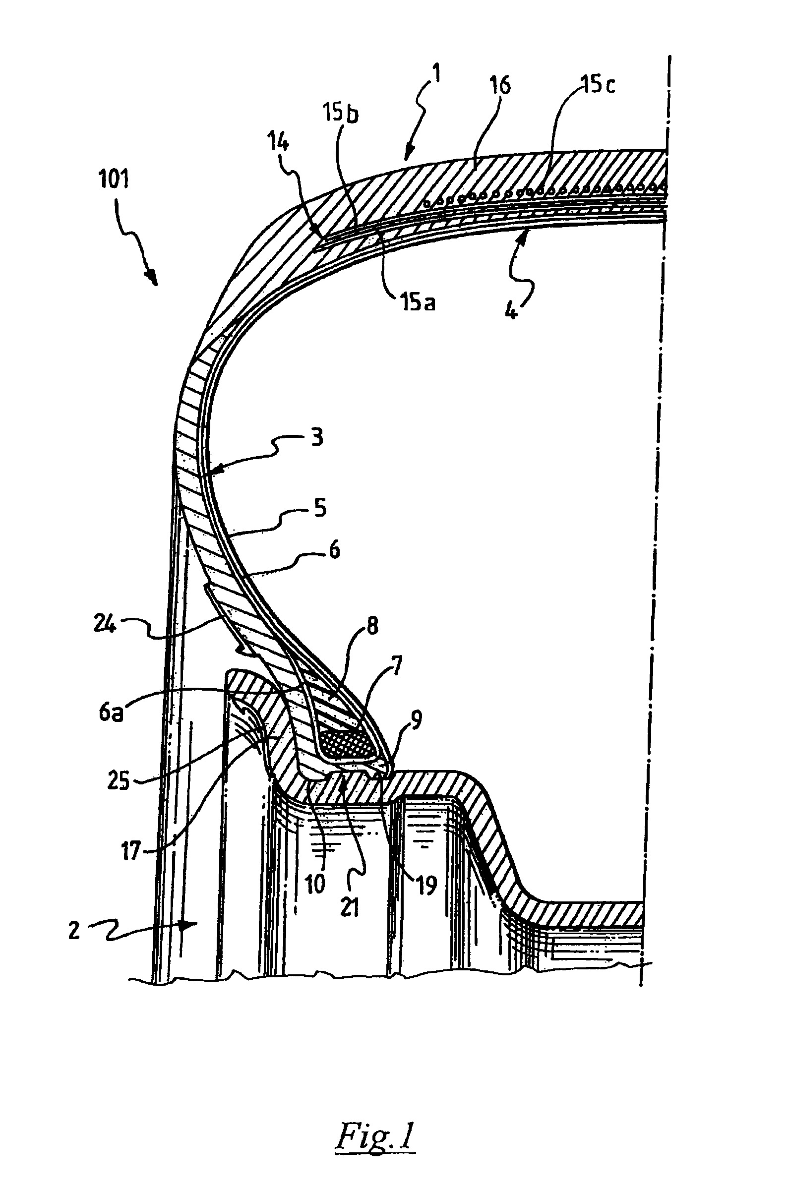
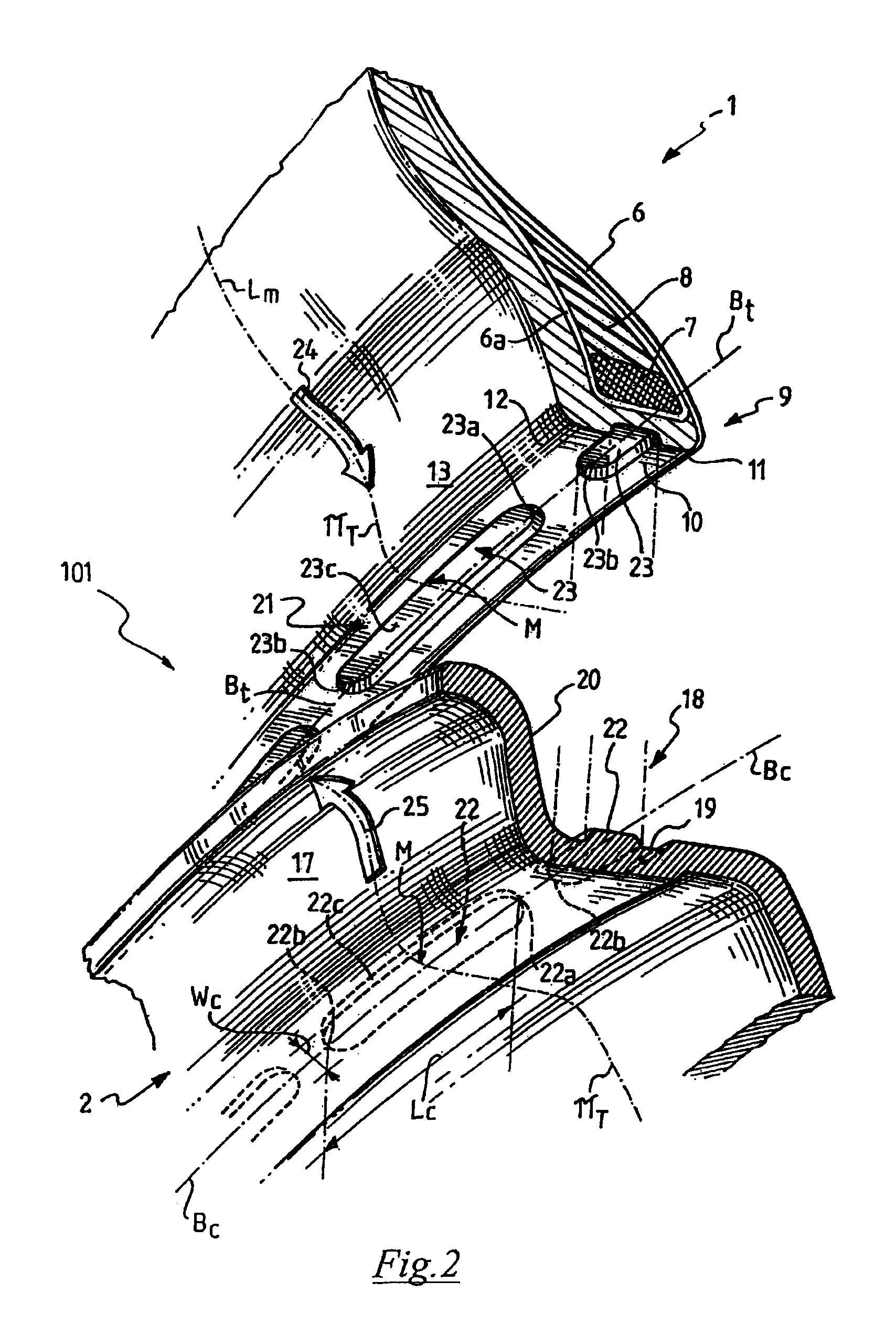
[0204]In the preferred embodiment of FIG. 10, an alternative embodiment of the wheel 101 according to FIGS. 1-5 is illustrated.

[0205]In this further preferred embodiment, at least one or preferably all the mechanical coupling elements 21 of the wheel 101 comprise a substantially tongue-shaped protrusion 22 radially extending from the rim 2 which, rather than being integrally formed as in the preferred embodiment illustrated in FIGS. 1-5, comprises in turn a plurality of portions 26, 27 spaced apart from each other along the circumferential direction.

[0206]In this case, the respective tongue seat 23 formed in the base 10 of the bead 9 therefore comprises a plurality of seat portions 28, 29 spaced apart from each other along the circumferential direction and adapted to house one of the respective portions 26, 27 of the substantially tongue-shaped protrusion 22.

[0207]Advantageously, this multiple portion configuration of the protrusion 22 and of the respective housing seat 23 allows t...

second embodiment

[0214]In the preferred embodiment of FIG. 11, an additional embodiment of the wheel 101 in accordance with FIGS. 6-9 is illustrated.

[0215]In this further preferred embodiment, at least one and preferably all the mechanical coupling elements 21 comprise a substantially tongue-shaped protrusion 22′ and a respective tongue seat 23′ for its housing configured in a manner complementary to that illustrated in FIG. 10 with reference to the preceding preferred embodiment of the wheel 101.

[0216]In other words, the wheel 101 comprises mechanical coupling elements 21 comprising in turn a substantially tongue-shaped protrusion 22′ radially extending from the base 10 of the bead 9 which, rather than being formed in one piece as in the preferred embodiment illustrated in FIGS. 6-9, comprises in turn a plurality of portions 26′, 27′ spaced apart from each other along the circumferential direction.

[0217]In this case, the respective tongue seat 23′ radially formed in the base portion 19 of the bead ...


PUM


Abstract

A wheel including a tire and a rim wherein the tire includes: a pair of beads, each of the beads being provided with a base, wherein the rim includes a pair of axially outer flanges defining respective bead housing seats, each of the bead housing seats including a base portion, and wherein the base of at least one of the beads and the base portion of the respective bead housing seat are mutually coupled by means of at least one mechanical coupling element, wherein the mechanical coupling element is provided with parts and has a length greater than its width, the length being lower than the circumference of the tire measured at the base of the bead and the width being lower than the axial width of the base of the bead and of the base portion of the respective bead housing seat.

Description

CROSS REFERENCE TO RELATED APPLICATION[0001]This application is a national phase application based on PCT / IT2008 / 000790, filed Dec. 23, 2008, the content of which is incorporated herein by reference.BACKGROUND OF THE INVENTION[0002]In a general aspect thereof the present invention relates to a wheel for vehicles.[0003]More particularly, the invention relates to a wheel for vehicles which has a preferred, although non-exclusive use, both on high or very high performance cars, so-called HP (High Performance) or UHP (Ultra High Performance) and on heavy vehicles adapted, for example, to cover long travels in motorways or for heavy uses.[0004]As is known, in a wheel for vehicles, whatever its final application, the tyre is coupled to the rim by means of the interaction between its radially inner end portions, the so-called beads, and the rim itself.[0005]More particularly, the rim comprises in the tyre coupling zone a pair of axially outer flanges extending at least in part along a radi...

Claims


Application Information

Patent Timeline
IPC IPC(8): B60B21/10B60C15/02B60C15/024
CPCB60C15/024B60B21/102
Inventor MANCINI, GIANNI
Owner PIRELLI TYRE SPA
Learn More