Ion sensing method for capacitive discharge ignition
a capacitive discharge and ion sensing technology, applied in the direction of instruments, machines/engines, mechanical equipment, etc., can solve the problems of loss of power, little if any adjustment of biasing voltage, and vibration created in the cylinder by knocking
- Summary
- Abstract
- Description
- Claims
- Application Information
AI Technical Summary
Problems solved by technology
Method used
Image
Examples
second embodiment
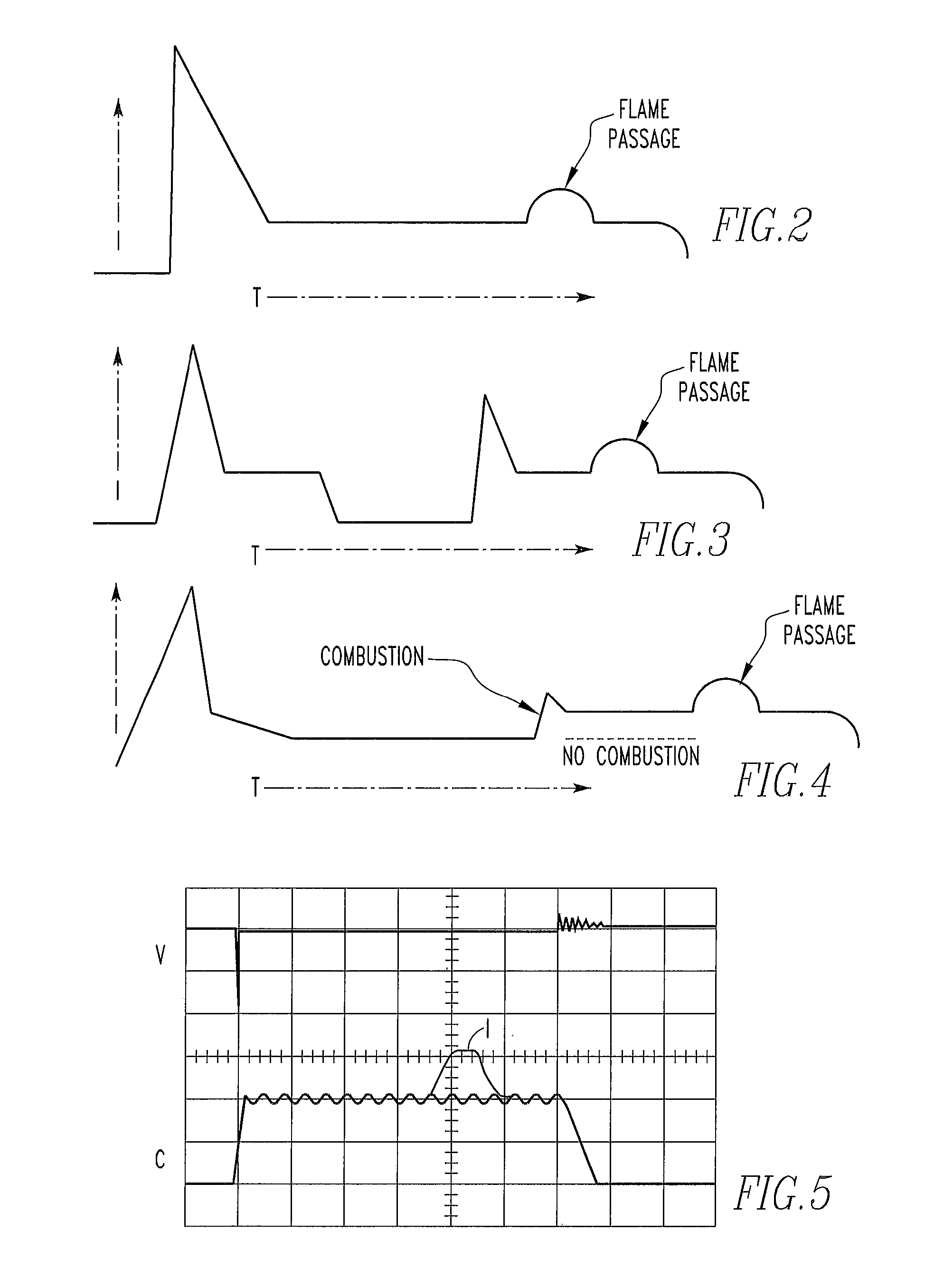
[0032]Referring to FIG. 3, according to this invention, after the initial closing period of the controllable switch to cause a spark breakdown and a period of time closing the controllable switch to implement a second spark breakdown, then maintaining a low voltage bias across the spark plug electrodes by controlling the ratio of opening and closing periods for a time sufficient to detect passage of the flame front between the spark plug electrodes.
third embodiment
[0033]Referring to FIG. 4, according to this invention, after the initial closing period of the controllable switch to cause a spark breakdown, a low voltage bias across the spark plug electrodes is maintained by controlling the ratio of opening and closing periods to cause a second spark breakdown only if the initial spark breakdown caused continuous combustion of the air / fuel mixture and then maintaining a low voltage bias across the spark plug electrodes by controlling the ratio of opening and closing periods for a time sufficient to detect passage of the flame front between the spark plug electrodes.
fourth embodiment
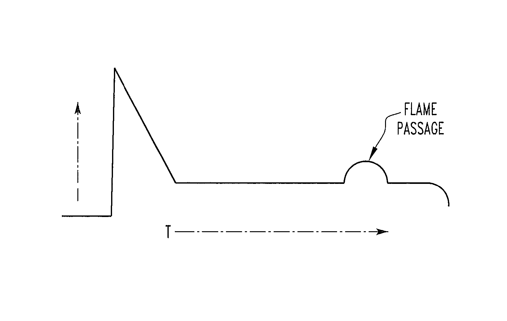
[0034]According to the invention, the total secondary current (spark plus ion current) which is established after the spark breakdown event is maintained at a virtually constant value for a fixed time long enough for the ion current to be sensed, by controlling the ratio of the opening and closing periods of the primary switch. The total current consisting of the spark current plus the ion current would normally decline rapidly after the spark breakdown thus forming a waveform which is triangular in shape. By forcing the total current value to be held to a constant value, the total current waveform will be rectangular in shape for the fixed constant current time period. In this embodiment, the higher the ion current present during this period of time, the less energy the primary drive circuit will need to provide to maintain this constant value of total current. The ratio of the opening and closing periods of the primary switch can then be used to determine the relative ion concentr...
PUM
| Property | Measurement | Unit |
|---|---|---|
| time | aaaaa | aaaaa |
| transfer energy | aaaaa | aaaaa |
| bias voltage | aaaaa | aaaaa |
Abstract
Description
Claims
Application Information
 - R&D
- Intellectual Property
- Life Sciences
- Materials
- Tech Scout
- Unparalleled Data Quality
- Higher Quality Content
- 60% Fewer Hallucinations
Browse by: Latest US Patents, China's latest patents, Technical Efficacy Thesaurus, Application Domain, Technology Topic, Popular Technical Reports.
© 2025 PatSnap. All rights reserved.Legal|Privacy policy|Modern Slavery Act Transparency Statement|Sitemap|About US| Contact US: help@patsnap.com


