Main bearing for crankshaft of internal combustion engine

a technology for internal combustion engines and bearings, which is applied in the direction of sliding contact bearings, mechanical equipment, rotary machine parts, etc., to achieve the effect of excellent foreign matter discharging efficiency

Active Publication Date: 2015-03-17
DAIDO METAL CO LTD
View PDF6 Cites 7 Cited by
  • Summary
  • Abstract
  • Description
  • Claims
  • Application Information

AI Technical Summary

Benefits of technology

[0009](2) Further, in the formation range of the second curved surface, an increasing rate of the gap per unit circumferential angle toward the circumferential end portion side from the circumferential central portion side of the half bearing is small, and therefore, on a downstream side of the gap region, the oil with a high pressure in the gap between the second curved surface on the circumferential central portion side of the half bearing and the journal surface (namely, on an upstream side of the gap region) accompanies the journal surface and is fed to the gap between the second curved surface on the circumferential end portion side of the half bearing and the journal surface (namely, the downstream side of the gap region). Thereby, on the downstream side of the gap region, “the pressure of the oil which accompanies the journal surface and flows to the circumferential end portion side in the gap between the second curved surface and the journal surface > the pressure of the oil in the oil groove” also tends to be established. Consequently, as shown in FIG. 14A, among the foreign matters in the oil groove, only a few of foreign matters flow to the gap between the second curved surface on the circumferential end portion side of the half bearing and the surface of the journal section, and most of the foreign matters advance to the circumferential end portion side of the oil groove, and easily enter the inner circumferential surface of the other half bearing. Furthermore, by the pressure of the oil which accompanies the journal surface and flows to the circumferential end portion side in the gap between the second curved surface and the journal surface as described above, a few of foreign matters that flow out to the gap also pass over the axial groove and are easily forced to flow to the inner circumferential surface of the other half bearing, as shown in FIGS. 14A and 14B.
[0010]Accordingly, an object of the invention of the present application is to provide a main bearing for a crankshaft of an internal combustion engine that is excellent in foreign matter discharging efficiency.

Problems solved by technology

(1) On an upstream side of the gap region, a gap between the second curved surface on a circumferential central portion side of the half bearing from the circumferential central portion of the second curved surface and the journal section surface of the crankshaft becomes too narrow with respect to the sizes of the foreign matters that enter the oil groove. Further, “the pressure of the oil which accompanies the journal surface and flows to the circumferential end portion side in the gap between the second curved surface and the journal surface > the pressure of the oil in the oil groove” is established, and the foreign matters are difficult to disperse while flowing to the gap between the second curved surface and the journal surface from the oil groove. Further, (a few of) foreign matters that are discharged into the gap are pushed into the second curved surface by the journal section surface of the crankshaft and accumulate.
(2) Further, in the formation range of the second curved surface, an increasing rate of the gap per unit circumferential angle toward the circumferential end portion side from the circumferential central portion side of the half bearing is small, and therefore, on a downstream side of the gap region, the oil with a high pressure in the gap between the second curved surface on the circumferential central portion side of the half bearing and the journal surface (namely, on an upstream side of the gap region) accompanies the journal surface and is fed to the gap between the second curved surface on the circumferential end portion side of the half bearing and the journal surface (namely, the downstream side of the gap region). Thereby, on the downstream side of the gap region, “the pressure of the oil which accompanies the journal surface and flows to the circumferential end portion side in the gap between the second curved surface and the journal surface > the pressure of the oil in the oil groove” also tends to be established. Consequently, as shown in FIG. 14A, among the foreign matters in the oil groove, only a few of foreign matters flow to the gap between the second curved surface on the circumferential end portion side of the half bearing and the surface of the journal section, and most of the foreign matters advance to the circumferential end portion side of the oil groove, and easily enter the inner circumferential surface of the other half bearing. Furthermore, by the pressure of the oil which accompanies the journal surface and flows to the circumferential end portion side in the gap between the second curved surface and the journal surface as described above, a few of foreign matters that flow out to the gap also pass over the axial groove and are easily forced to flow to the inner circumferential surface of the other half bearing, as shown in FIGS. 14A and 14B.

Method used


Image

  • Main bearing for crankshaft of internal combustion engine
  • Main bearing for crankshaft of internal combustion engine
  • Main bearing for crankshaft of internal combustion engine

Examples


embodiment 1

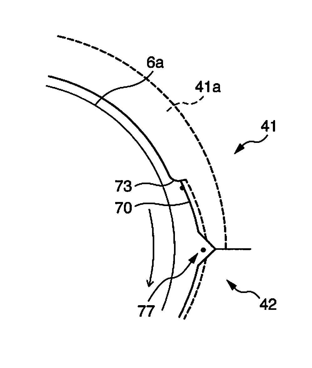
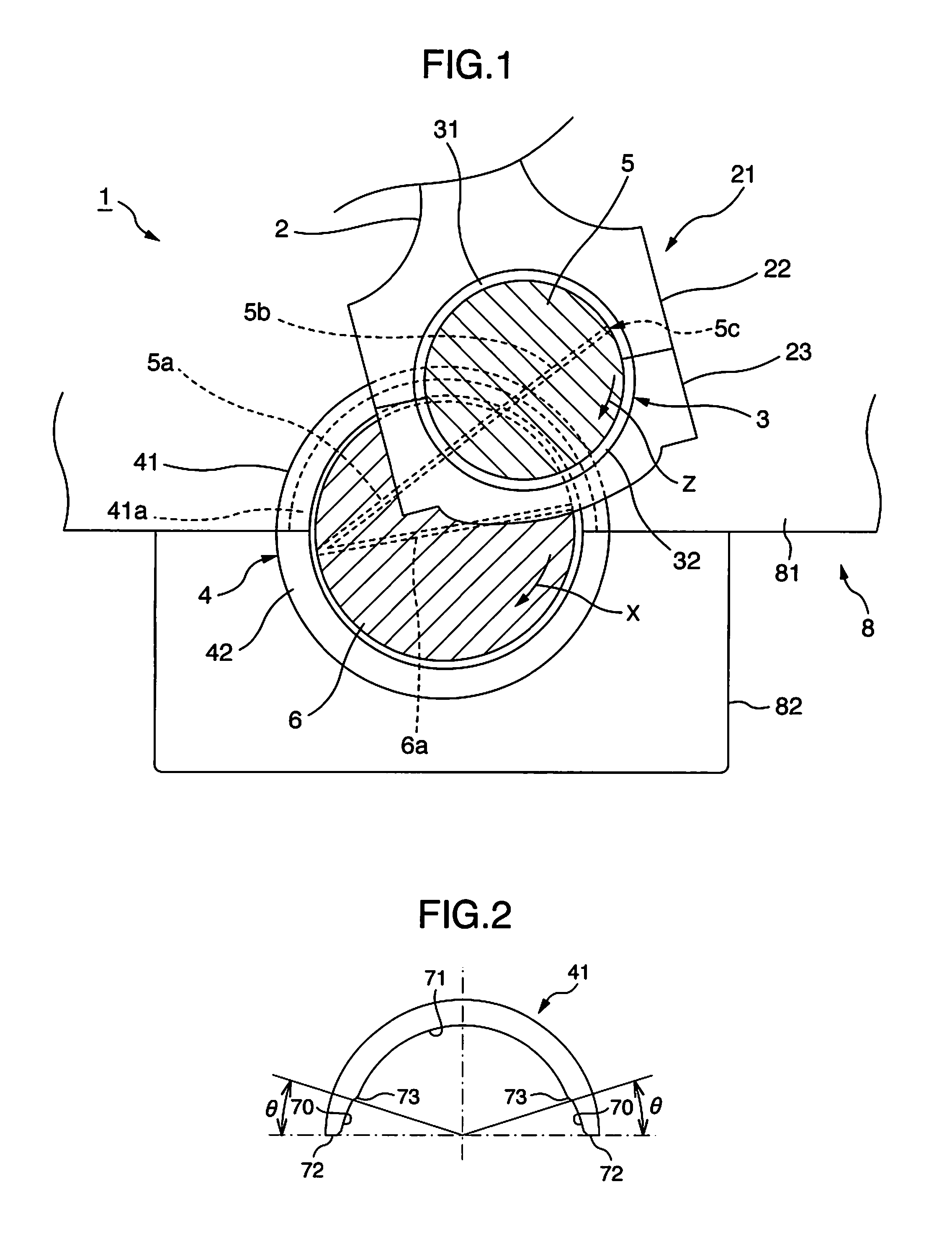
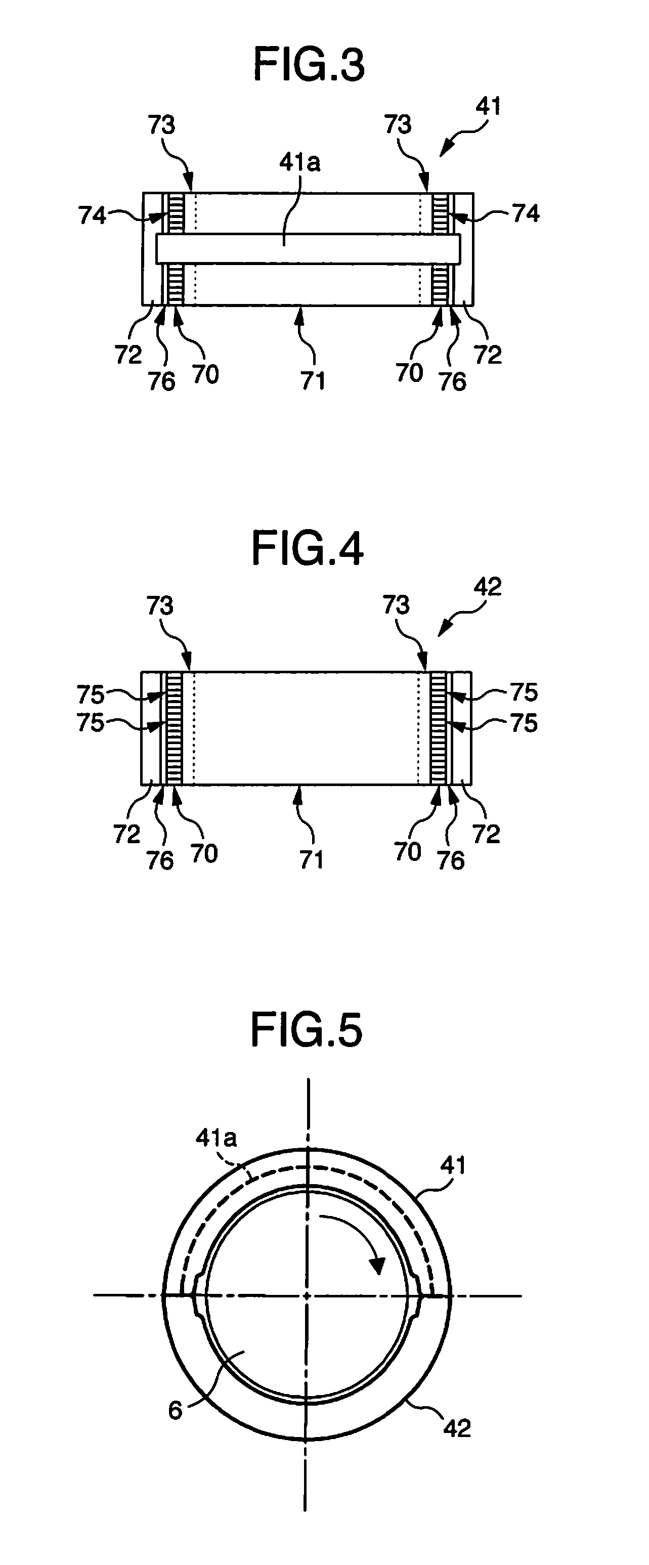
[0055]As is understood from FIGS. 3 and 5, the oil groove 41a which is formed on the inner circumferential surface of the half bearing 41 is formed to extend through the central portion in the circumferential direction, and open to both end surfaces 72 in the circumferential direction of the half bearing 41. A depth of the oil groove 41a is constant throughout an entire length in the circumferential direction of the oil groove 41a. Note that in the main cylinder portion 71, the depth of the oil groove 41a mentioned here refers to a depth to an oil groove bottom surface from an inner circumferential surface of the main cylinder portion 71, whereas in the crush relief portion 70 and the transition region 73, the depth of the oil groove 41a refers to a depth from a virtual inner circumferential surface 71v in the case in which the crush relief portion 70 and the transition region 73 are not formed.

[0056]As is understood from FIG. 3, the oil groove 41a is disposed in a center of a width...

embodiment 2

[0084]As shown in FIGS. 12 and 13, unlike the one half bearing 41 of embodiment 1, the oil groove 41a is formed in such a manner that a depth from the main cylinder surface becomes maximum in the central portion in the circumferential direction of the half bearing 41, and becomes gradually smaller toward both end portions in the circumferential direction. Both end portions in the circumferential direction, of the oil groove 41a are positioned in the crush relief portion 70, and on a front side from the end portion in the circumferential direction of the oil groove 41a, a surface of the crush relief portion 70 having a plurality of crush relief grooves is formed. The other configuration is the same as the configuration of the half bearing 41 of embodiment 1.

[0085]In embodiment 2, as shown in FIG. 13, in the crush relief portion 70 of the other half bearing 42 which is paired with the one half bearing 41, a plurality of crush relief grooves 75 extending in the circumferential directio...


PUM


Abstract

A main bearing for a crankshaft of an internal combustion engine has first and second half bearings forming an axial groove on an inner circumferential side of a butting portion. Each half bearing has a main cylinder portion including a central portion in a circumferential direction, and crush relief portions each extending toward the central portion from an end surface of the half bearing in the circumferential direction with a center angle of 3° to 15°. A plurality of crush relief grooves are formed in each crush relief portion to extend in the circumferential direction and communicate with the axial groove. The first half bearing has an oil groove extending in the circumferential direction and a transition region having an inward protruding curved surface with a wall thickness becoming thinner toward the crush relief portion from the main cylinder portion.

Description

BACKGROUND OF THE INVENTION[0001](1) Field of the Invention[0002]The invention of the present application relates to a main bearing for supporting a crankshaft of an internal combustion engine.[0003](2) Description of the Related Art[0004]A crankshaft of an internal combustion engine is supported at a journal section thereof by a cylinder block lower part of the internal combustion engine via a main bearing made of a pair of half bearings. For the main bearing, a lubricating oil that is discharged by an oil pump is fed into a lubricating oil groove that is formed along an inner circumferential surface of the main bearing through a through-port that is formed in a wall of the main bearing from an oil gallery that is formed in a cylinder block wall. Further, a first lubricating oil path is formed by being penetrated in a diameter direction of the journal section, and both end openings of the first lubricating oil path communicate with the lubricating oil groove of the main bearing. Fu...

Claims


Application Information

Patent Timeline
Patent Type & Authority Patents(United States)
IPC IPC(8): F16C33/10F16C9/02
CPCF16C9/02F16C33/1065F16C17/022F16C33/046F16C2240/40F16C2240/42F16C2360/22
Inventor KAWASHIMA, YUKIKOUSHIMA, MOTOHIKO
Owner DAIDO METAL CO LTD
Why Eureka
Try Eureka