Device for fastening

a technology for devices and fastening, applied in the direction of threaded fasteners, fastening means, screws, etc., can solve the problem of relative harmful movement between the elements to be fastened, and achieve the effect of simple, effective and economical

Active Publication Date: 2015-03-17
HOWMET FIXATIONS SIMMONDS SAS
View PDF25 Cites 1 Cited by
  • Summary
  • Abstract
  • Description
  • Claims
  • Application Information

AI Technical Summary

Benefits of technology

[0009]The elastic deformation of the thinned portion makes it possible to obtain a constant pressure on the threading of the screw during the tightening.
[0012]The threading can also comprise a zone wherein the pitch is reduced, with the forcing of the threaded rod in the threading making it possible to deform the thread and as such guarantee the braking during the screwing.
[0019]In this way, for the same angular position of the nut in relation to the threaded rod, the possibilities of assembling the ring are doubled. As is indicated hereinafter, assembly clearances between the ring on the one hand and the skirt of the nut or the threaded rod on the other hand, can make it possible to absorb angular offsets less than one half pitch. As such, regardless of the position of the nut in relation to the threaded rod, the assembly of the ring is always possible.
[0021]The possibilities for assembly are as such further increased. In the same way as previously, the assembly clearances between the ring on the one hand and the skirt of the nut or the threaded rod on the other hand, make it possible to absorb angular offsets less than a quarter of a pitch.

Problems solved by technology

During the flight of an aircraft, the vibrations generated can cause a nut to become loose, causing a relative harmful movement between the elements to be fastened, and even the disconnecting thereof.

Method used


Image

  • Device for fastening
  • Device for fastening
  • Device for fastening

Examples


Embodiment Construction

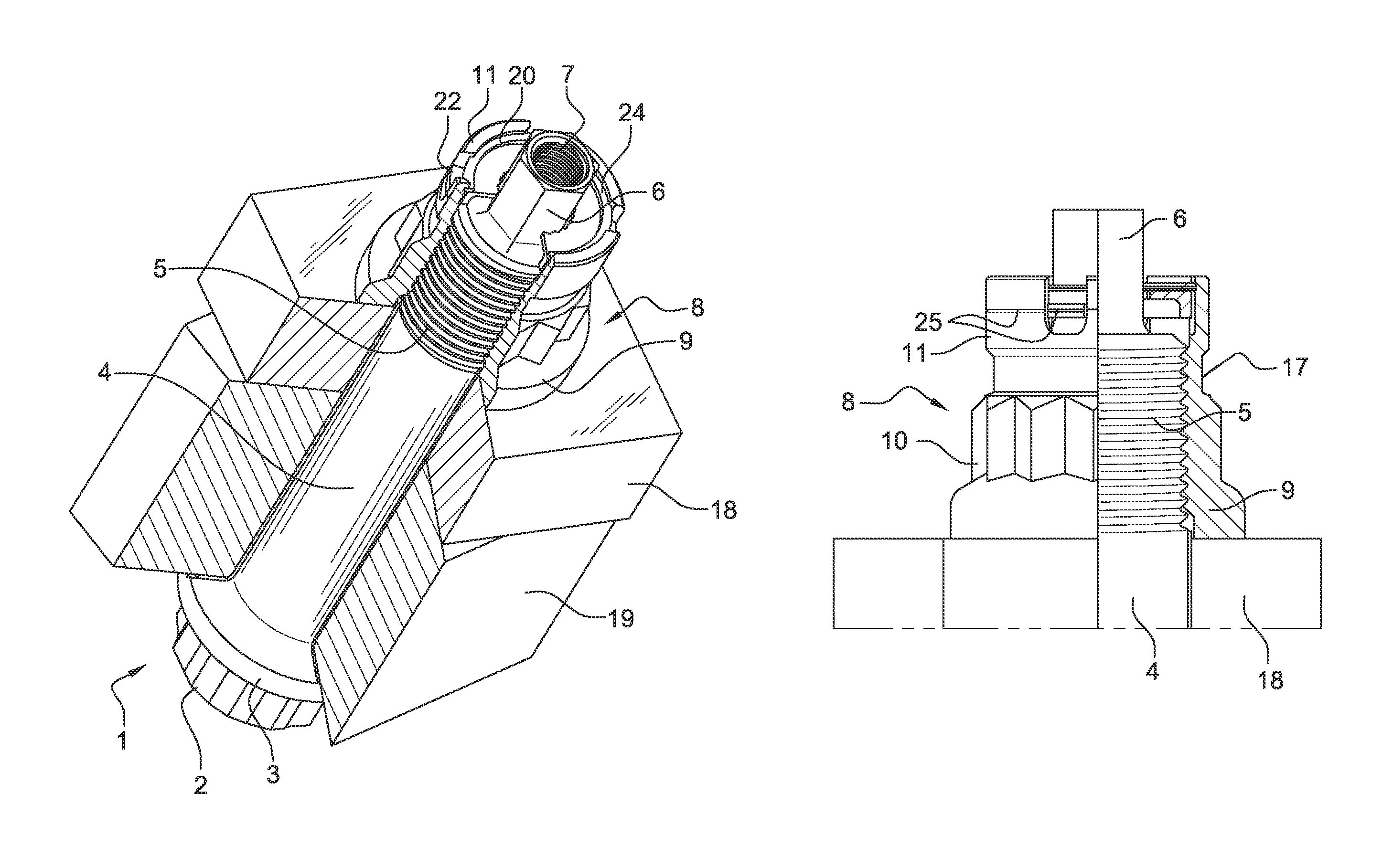
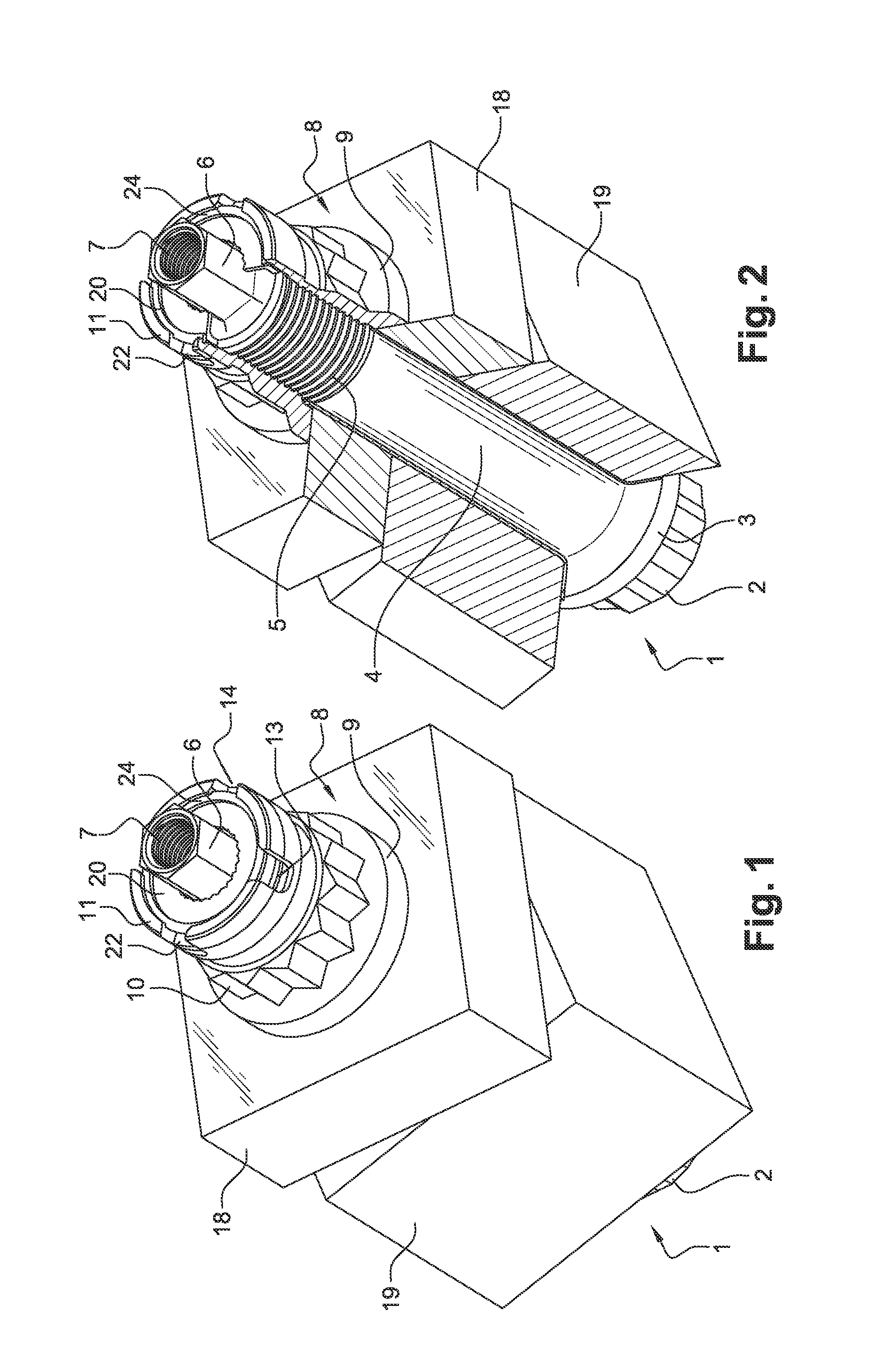
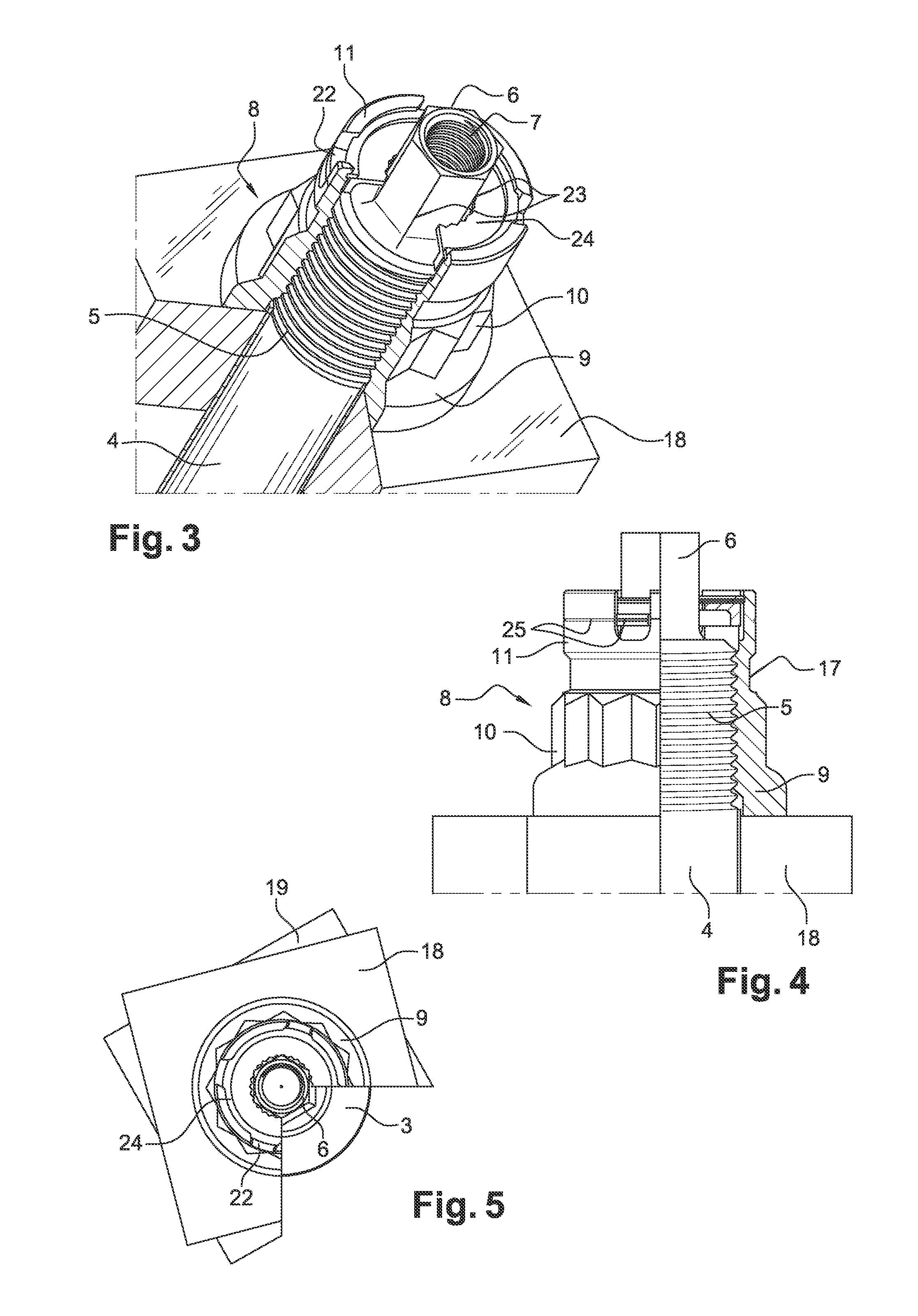
[0036]An embodiment of a device for fastening is shown in FIGS. 1 to 5. This device comprises a screw 1, which can be seen better in FIG. 6, comprising a head 2 provided with a flange 3, from which extends a cylindrical rod 4 of which only the end 5 is threaded.

[0037]The end of the rod is extended by a portion 6 of reduced and hexagonal section, having a threaded hole 7 in the center thereof, intended for assembling another screw (not shown).

[0038]A nut 8 is screwed onto the threaded end 5 of the screw 1, this nut 8 comprising a widened base 9, a zone of a star or bi-hexagonal section used for the tightening of the nut, and a skirt 11 of cylindrical shape extending axially and wherein are arranged two pairs of notches 12 to 15 (see FIGS. 7 and 8). The notches 12, 13 and 14, 15 of the same pair are diametrically opposite one another, with two successive notches being offset angularly by a non-orthogonal angle.

[0039]More precisely, the angular offset a between the notches 12 and 14 an...


PUM


Abstract

A device for fastening includes a threaded rod, a nut that can be screwed on the rod and elements for locking the nut in rotation in relation to the threaded rod including an intermediary ring mounted between a skirt of the nut and an end of the threaded rod, this ring including rotational coupling elements with the end of the threaded rod and rotational coupling elements with the skirt of the nut. The nut is elastically deformable to tightening during the screwing on the threaded rod.

Description

FIELD AND BACKGROUND OF THE INVENTION[0001]This invention relates to a device for fastening, intended in particular for the aeronautics field.[0002]In such a field, it is particularly important to ensure the proper fastening of the various elements. During the flight of an aircraft, the vibrations generated can cause a nut to become loose, causing a relative harmful movement between the elements to be fastened, and even the disconnecting thereof.[0003]In order to prevent this, FR 2 854 213, in the name of the Applicant, proposes a device for fastening comprising a threaded rod, a nut that can be screwed on the rod and means for locking the nut in rotation in relation to the threaded rod comprising an intermediary ring mounted between the nut and an end of the threaded rod. This ring comprises rotational coupling means with the end of the threaded rod and rotational coupling means with the nut.[0004]Such a device makes it possible to prevent in a relatively sure manner any rotation o...

Claims


Application Information

Patent Timeline
Patent Type & Authority Patents(United States)
IPC IPC(8): F16B39/10F16B39/284
CPCF16B39/284F16B39/10
Inventor CORMIER, ARNAUD
Owner HOWMET FIXATIONS SIMMONDS SAS
Why Eureka
Try Eureka