Fastening device

a technology of fastening device and guiding element, which is applied in the direction of snap-action fasteners, screws, garments, etc., can solve the problems of affecting the operation of the fastening device, so as to achieve the effect of simple process, simple means, and easy scaling up a structur

Inactive Publication Date: 2015-03-17
ITW SVERIGE
View PDF20 Cites 11 Cited by
  • Summary
  • Abstract
  • Description
  • Claims
  • Application Information

AI Technical Summary

Benefits of technology

[0013]Furthermore comprises the main portion guiding elements in order to guide the fastening device when inserting the fastening device through a slot or mounting aperture and, in addition, resilient elements. The resilient elements are intended to be inserted into the aperture as far as they will provide a locking of the fastening device. The main portion is thus inserted into the aperture such a distance that the resilient elements will be located in its locking position. When the main portion of the fastening device is inserted into the aperture will the resilient elements be compressed and pressed radially inwards towards the centre of the main portion in order to at a later stage, when the resilient elements have passed the edge of the hole, resiliently move back and thus provide a locking of the fastening device by being in contact with the rim on the inside of the aperture. It is not necessary that the resilient elements completely pass by the rim of the aperture but they may for example be provided with one or several shoulders such that the elements are adapted to be able to be used for elements (e.g. panels, plates, covers and the like) having different thickness which shall be attached to each other or onto load bearing structures. The fastening device is thus located in its locking position and its head prevents that the fastening device will enter completely through the aperture and the resilient elements prevents that the fastening device will slip back through the aperture and out of the aperture once again.
[0015]The present fastening device and its fairly simple construction results in that it may be easy to produce in a one-step process by injection moulding or compression moulding. Furthermore, its unique design provides a safe insertion in a mounting aperture associated with a very small risk to damage any part of the fastening device while at the same time the force needed to insert and mount may be distributed such that the force will be fairly evenly distributed during the entire insertion procedure of the fastening device in the mounting aperture.
[0016]According to one embodiment is the fastening device designed such that the vanes, which are used to form the guiding element, are shaped such that their extension in the radial direction decreases along its extension in axial direction from the base end of the main portion to the distal end of the main portion. The vanes are thus shaped such that a projection of a circle, perpendicular to the axial direction of the main portion, having its centre in the middle of the main portion and a periphery at the distal end of the vanes along the axial extension of the main portion, forms a more or less conical shape having a broad base at its end portion which is located at the head and which decreases along the axis of the main portion. Preferably form the vanes an apex at the distal end of the fastening device. A sharp, pointed end portion will make it easier to fit the fastening device into the mounting aperture and may thus be used as a pointer in order to direct the fastening device into a proper position if the inside of the aperture is provided with some kind of guiding rail or guiding hole which is adapted to guide the apex, and thus the fastening device, to a desired position. It is however not necessary that the guiding elements are arranged such that they form a sharp point but in certain cases it may be desired to have a fairly blunt end point such that its shape essentially corresponds to a truncated cone. A blunt point, or truncated cone, will on the one hand side make it more difficult to insert the clip in the mounting aperture while on the other hand side it means that the guiding may be better when the clip once is positioned in the aperture since the fastening device will automatically be guided to a more central position as soon as the fastening device is at least partly inserted in the mounting aperture due to the fact that the free motion margin between the edge of the aperture and the guiding arrangement is smaller from the start in this case.
[0017]The design of the shape of the fastening device will make it possible to adapt it easily to comprise a more blunt apex since it only implies that the vanes which are comprised in the guiding element are cut off at an appropriate distance from its base end (or, which may seem more logical, are moulded in such a way) such that a blunt apex (truncated cone) is achieved.
[0026]Below follows a disclosure of a specific embodiment of the invention in which the fastening device has been provided with 3 vanes which makes up the guiding arrangement. It is obvious that the invention also could be performed with further vanes, for example 4, 5, 6 or more, and with further resilient elements. However, the number of vanes and resilient elements does not need to be the same and it is for example possible to imagine three vanes of which each one has been provided with two resilient elements or that 6 vanes are used and only every second vane has been provided with a resilient element. It may however be difficult to use numerous vanes, and thereto attached resilient elements, for fastening devices having small dimensions since it may be difficult to manufacture very delicate and advanced structures in an easy way. The described fastening devices is intended to function in holes or apertures having a diameter of about 8 mm and it is thus often hard to manufacture such fastening devices provided with too many vanes or an overall complicated geometry. Even though the fastening devices are intended for fairly small apertures is it obvious that it should function in larger apertures or holes. As a general rule it may be stated that a clips or fastening device which may be manufactured and used in a small hole or aperture may be scaled up and be used in a larger hole since such a manufacturing process as injection moulding or compression moulding allows easily to scale up a structure while it is often associated with complications to scale down the size of a functioning clip such that it may be made using simple means and a simple process.

Problems solved by technology

In many cases are these made up of the same element which results in, when there is a heavy pressure or load on the fastening device in order to guide it properly, there is a great risk that the guiding elements, which also are the snap-in locking elements, may be damaged.
Since the snap-in locking elements must be flexible and able to bend in the guiding direction, i.e. in the direction of centering the fastening device in the aperture, and since this is the same direction in which they shall be able to resiliently be compressed in order to enter through the aperture and later on resiliently move back into a locking position, is it hard to combine these two functions in one single element.
A well working centering implies rigid elements which in this case will contribute to difficulties in inserting the fastening device.
Such an attachment often makes it difficult to distribute the need of forces under the insertion procedure in order to push the fastening device into its locking position.

Method used


Image

  • Fastening device
  • Fastening device
  • Fastening device

Examples


Embodiment Construction

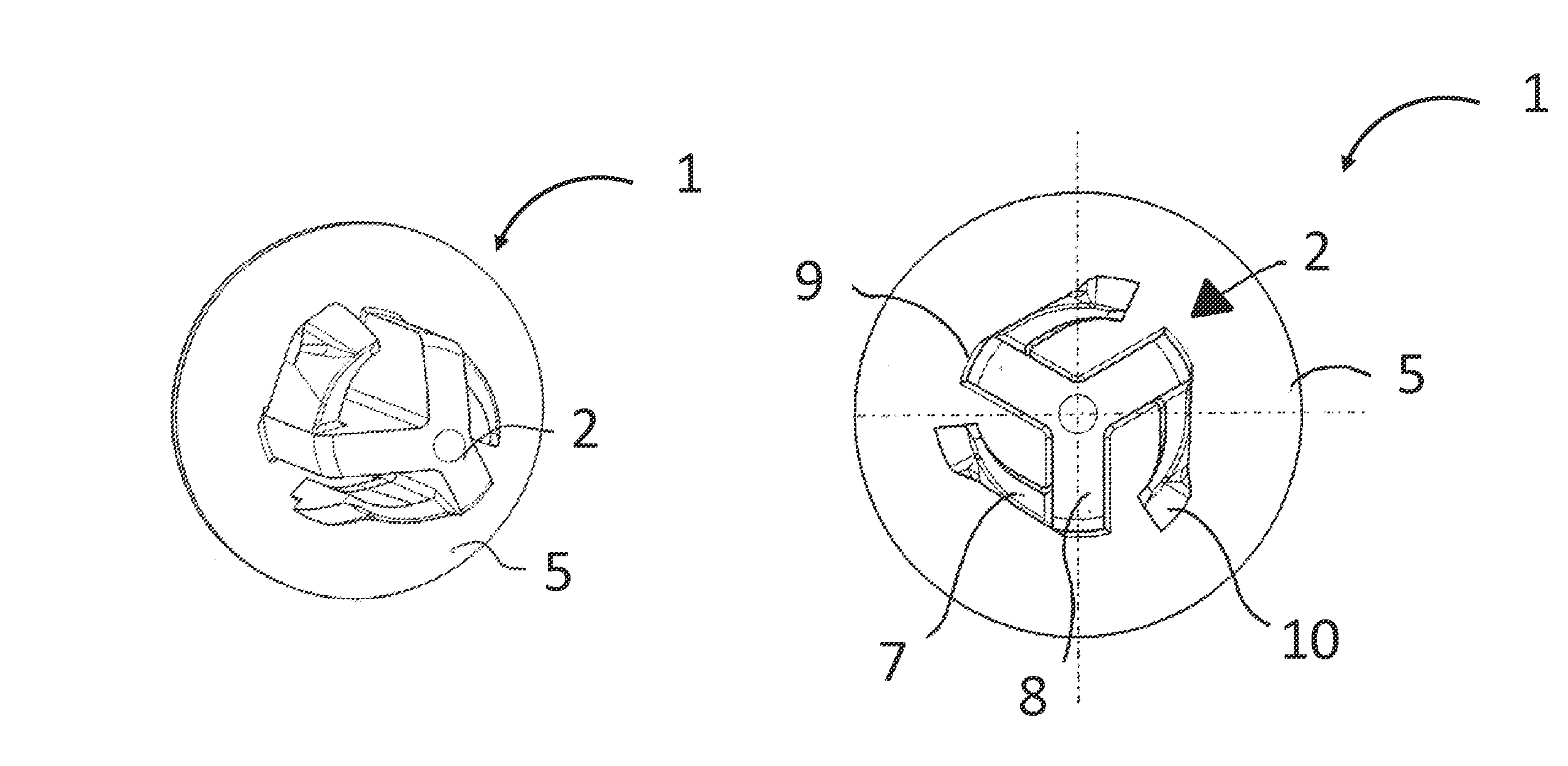
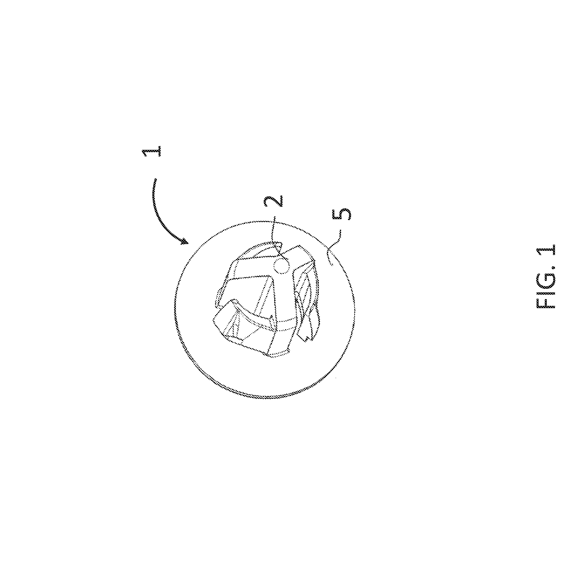
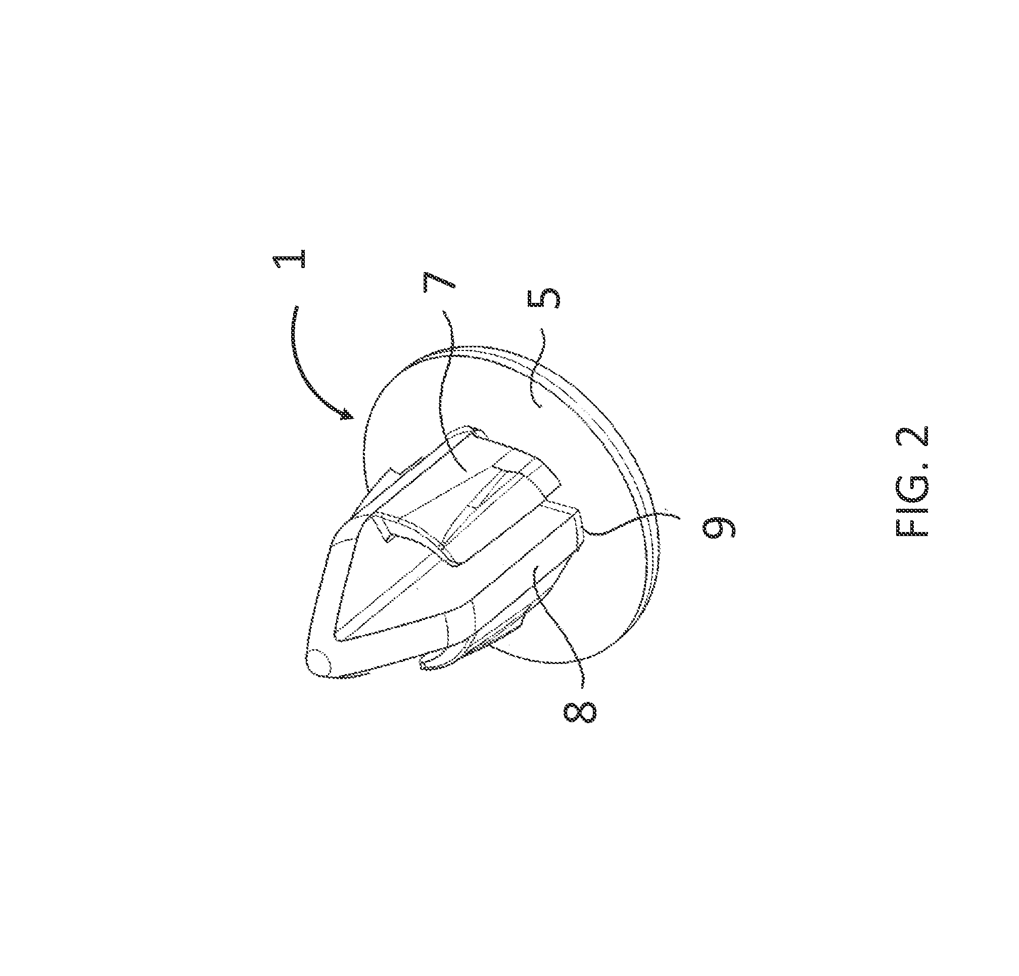
[0036]In FIG. 1-9 is described an embodiment of a fastening device 1 according to the invention. In FIG. 1 is described the fastening device 1 comprising a main portion 2 and a head 5. It is most clearly shown in FIG. 6 that the main portion 2 is provided with a base end portion 3 and a distal end portion 4. The main portion 2 comprises guiding elements 6 and resilient elements 7. In the disclosed embodiment comprises the guiding element three vanes 8. The construction of the main portion 2 is probably most clearly shown in FIG. 4 wherein a cross sectional view of the main portion 2 comprising the guiding element 6 is shown as the lined area comprising three vanes 8 and three resilient elements 7 attached to the vanes 8. The vanes 8 are spaced apart equidistantly from each other on the surface of the head 5 such that the peripheral parts of the bases 9 of the vanes 8 (most clearly shown in FIG. 2) are located at an equidistant distance from the centre of the main portion 2 (most cle...


PUM


Abstract

A fastening device comprising a main portion having a base end portion and a distal end portion wherein its base end is attached to a head intended to be in contact with a rim at the outer side of an aperture when the fastening device is located in the aperture. The main portion is provided with guiding elements in order to guide the fastening device when inserted into the aperture and resilient elements which during insertion will be pressed inwards in order to at a later stage, when the resilient elements have passed the rim of the aperture, resiliently move back and thus provide a locking of the fastening device by being in contact with the rim on the inside of the aperture. The guiding element is provided with at least three vanes which are attached at its bases to the head such that they are located at an essentially equidistant spacing from the centre point. The resilient elements are made up by segments which only are attached to the fastening device along one side of the segments to the vanes such that they are protruding from the vanes and extend in a direction towards an adjacent vane.

Description

RELATED APPLICATIONS[0001]The present application is national phase of PCT / SE2008 / 050845 filed Jul. 7, 2008, and claims priority from Swedish Application Number 0701677-7 filed Jul. 9, 2007, the disclosures of which are hereby incorporated by reference herein in their entirety.TECHNICAL FIELD[0002]The invention relates to a fastening device (clip) which is used to attach different elements to each other, for example when mounting interior panels onto vehicles.BACKGROUND ART[0003]In order to join together devices, for example attachment of different kinds of panels in vehicles, screw joint reinforcements have earlier traditionally been used. However, screw joint reinforcements suffer from a number of disadvantages. The head of the screw will remain visible after attachment and should in some way be hidden or a less aesthetic appearance of the installation must be accepted. Furthermore, the mounting of a screw joint reinforcement is time consuming. In addition, such a mounting must be...

Claims


Application Information

Patent Timeline
Patent Type & Authority Patents(United States)
IPC IPC(8): F16B21/08
CPCF16B21/086F16B21/084Y10T24/42
Inventor OSTERGREN, KRISTIAN
Owner ITW SVERIGE
Why Eureka
Try Eureka