
Electronic injector

a technology of electronic injectors and injectors, which is applied in the direction of suction devices, infusion needles, other medical devices, etc., can solve the problems of preventing patients from using them regularly, suffering adverse effects, and certain patients being unlikely or unable to follow the drug regimen

Active Publication Date: 2015-03-17
MEDTRONIC MIMIMED INC
View PDF82 Cites 10 Cited by
  • Summary
  • Abstract
  • Description
  • Claims
  • Application Information

AI Technical Summary

Benefits of technology

The patent describes an electronic on-body injector that can deliver fluids to patients through an injection device. The injector includes a fluid reservoir, a MEMS pump, and a bolus injection needle. The bolus needle can be activated to close a gap and deliver the fluid to the patient. The injector can also deliver a predetermined bolus volume to the patient by activating the MEMS pump. The electronic injector provides a convenient and precise method for delivering fluids to patients.

Problems solved by technology

Certain patients are unlikely or unable to follow the drug regimen required to maintain their medical condition under control.
Some patients are squeamish about injecting the drug themselves and others suffer adverse effects from repeated injections, such as bruising at the injection site.
Problems with existing mechanical insulin pens also discourage the patient from using them regularly.
Mechanical insulin pens are bulky, requiring an extendable dial and a large working chamber, making the mechanical insulin pen itself large.
Use of the mechanical insulin pen is also indiscreet: the patient must manually calculate the dosage, manually crank a large noisy visible dial to set the dosage, and then perform the injection with the large device.
The mechanical components are also ill-suited to conversion to electronic operation.
Unfortunately, injection ports still require that the patient administer the therapeutic agent repeatedly throughout the day.
Injection ports with dedicated reservoirs allowing bolus injection have been developed, but maintain a continuous flow path and run the risk of inadvertent bolus injection.
Although these problems can be remedied with a dedicated electronic insulin pump, many patients are unwilling or unable to use a dedicated insulin pump due to the expense and complication.

Method used


Image

  • Electronic injector
  • Electronic injector
  • Electronic injector

Examples


Embodiment Construction

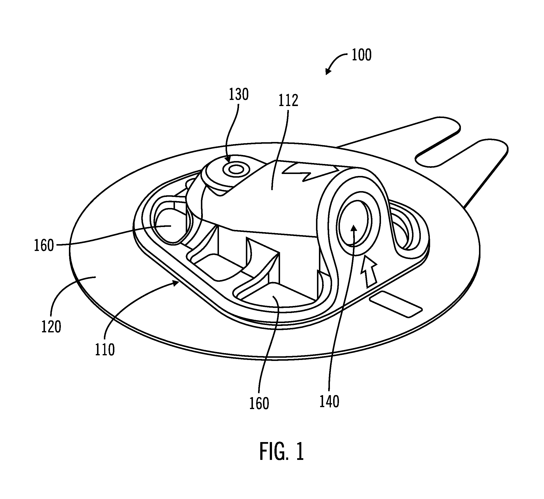
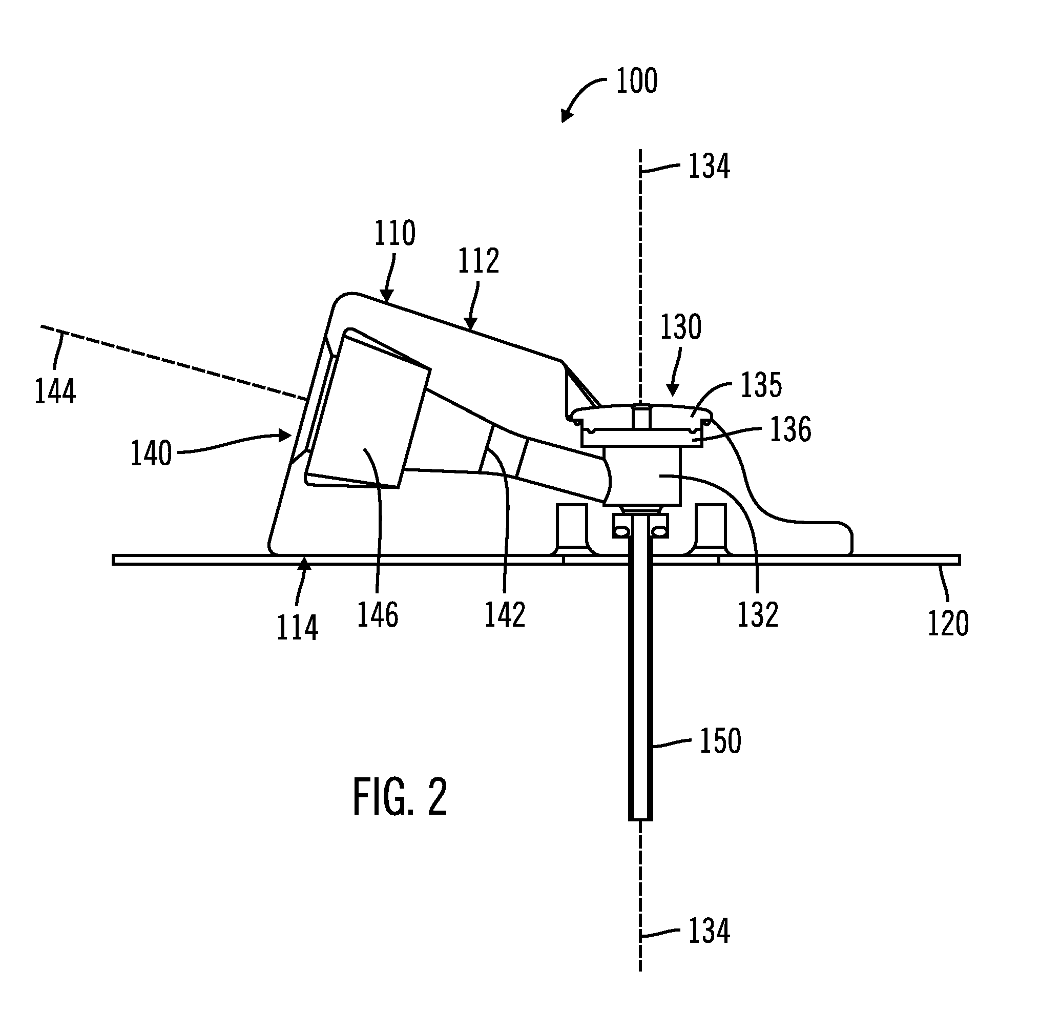
[0039]FIGS. 1-5C, in which like elements share like reference numbers, are various views of one embodiment of an injection device made in accordance with the invention. The injection device includes an introducer port along an introducer axis and an injection port along an injection axis, with the injection axis being non-collinear with the introducer axis. In this embodiment, the injection axis is at an angle to and intersects with the introducer axis.

[0040]FIG. 1 is a perspective view of the injection device 100 including a body 110 and a patch 120 attached to the body 110. The patch 120 is operable to adhesively attach the injection device 100 to a patient (not shown). The body 110 has a port face 112, with an introducer port 130 and an injection port 140 on the port face 112. The introducer port 130 is used to place a delivery tube subcutaneously in the patient. The injection port 140 is used by the patient to inject a therapeutic agent, which as defined herein can be any liquid...


PUM


Abstract

An electronic injector including an electronic on-body injector for use with a patient to deliver a fluid through an injection device. The electronic on-body injector includes a fluid reservoir; a MEMS pump; a bolus injection needle, the bolus injection needle having a bolus injection needle tip aligned with the injection port, the bolus injection needle being slideably biased away from the injection port to define a gap; and a bolus needle button operably connected to the bolus injection needle to slide the bolus injection needle along the injection axis. The bolus needle button is operable to advance the bolus injection needle tip to close the gap and advance the bolus injection needle tip into the injection port to form a bolus injection flow path. The bolus needle button is further operable to activate the MEMS pump to deliver a predetermined bolus volume.

Description

CROSS REFERENCES TO RELATED APPLICATIONS[0001]This application is a continuation-in-part of and claims the benefit of U.S. patent application Ser. No. 14 / 052,929, filed on Oct. 14, 2013, entitled THERAPEUTIC AGENT INJECTION DEVICE, which is incorporated by reference in its entirety herein.TECHNICAL FIELD[0002]The technical field of this disclosure is personal medical systems, particularly, electronic injectors.BACKGROUND OF THE INVENTION[0003]Certain medical conditions or diseases require that patients intermittently inject a drug or therapeutic agent subcutaneously to maintain the medical condition or disease under control. Multiple daily injections (MDIs) may be required. One such medical condition is diabetes, for which insulin is injected to regulate blood glucose. An estimated twenty-six million people in the United States, or about 8% of the population, have diabetes. This percentage is expected to increase in the near-term as the population ages.[0004]Certain patients are unl...

Claims


Application Information

Patent Timeline
Patent Type & Authority Patents(United States)
IPC IPC(8): A61M1/00A61M5/145
CPCA61M5/145A61M2005/14506A61M5/14248A61M2005/1585A61M2005/1586A61M2205/825
Inventor ASKARINYA, MOHSENBROWN, RICHARD L.CHONG, COLIN A.KINZIE, PATRICK W.SCHULHAUSER, RANDALCHERRY, JEFF M.STEVENSON, TYLER S.
Owner MEDTRONIC MIMIMED INC
Learn More