
Method of arresting fatigue crack growth in metal member, and fatigue crack growth-arrested metal member

a metal member and growth technology, applied in the direction of mechanical means, building repairs, instruments, etc., can solve the problems of fatigue crack growth, fatigue crack growth, and another fatigue crack, and achieve the effect of arresting the growth of fatigue cracks

Active Publication Date: 2015-03-24
IHI CORP
View PDF5 Cites 6 Cited by
  • Summary
  • Abstract
  • Description
  • Claims
  • Application Information

AI Technical Summary

Benefits of technology

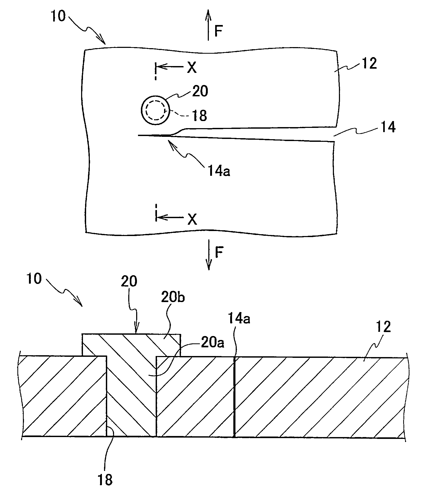
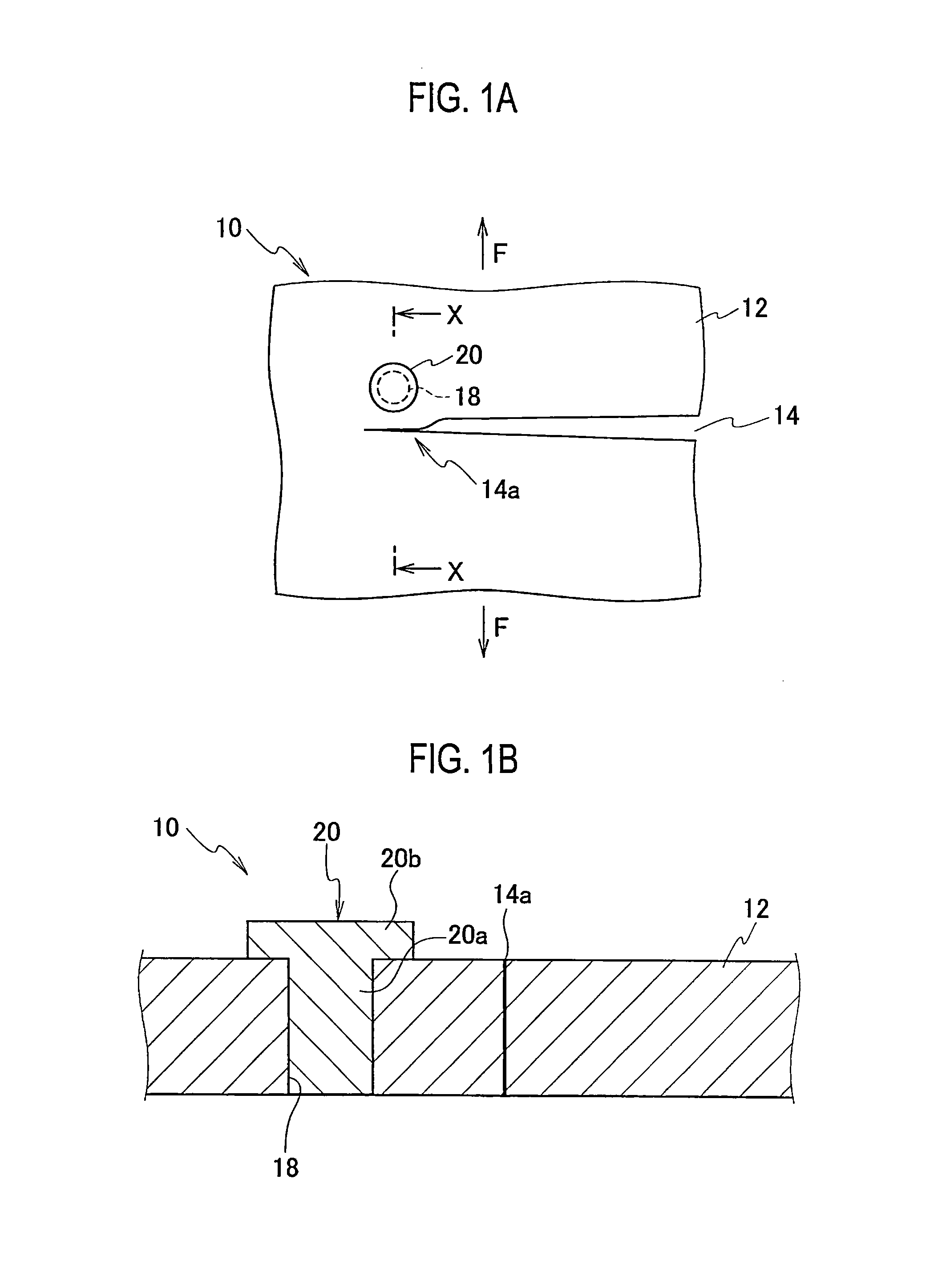
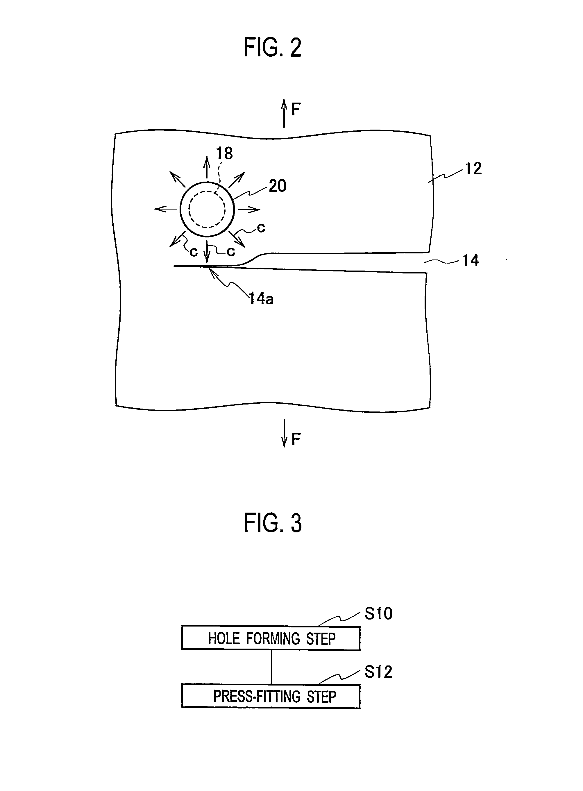
The patent text discusses a method for stopping fatigue cracks in a metal member. The method involves creating small round holes called stop-holes to reduce stress concentration at the tip of the crack. These stop-holes can help temporarily relax the stress concentration, but they can also attract other fatigue cracks and allow them to grow further. However, the text also explains a method for closing fatigue cracks through a peening process which can be difficult to apply to cracks inside the metal member. The method described in the text helps to arrest the growth of fatigue cracks in the metal member by using a compressive stress force to act on the tip of the crack. This can further prevent the fatigue crack from growing and causing damage to the metal member.

Problems solved by technology

Although the stop-hole method can temporarily relax the stress concentration by providing the round hole to the fatigue crack tip, another fatigue crack is likely to occur and grow from the round hole as a stop-hole due to the action of repeatedly applied stress.
The method of closing the fatigue crack through the peening process or the like on the crack surface has a difficulty in closing a fatigue crack inside the metal member in the plate-thickness direction, and there remains a possibility that the fatigue crack may grow further.

Method used


Image

  • Method of arresting fatigue crack growth in metal member, and fatigue crack growth-arrested metal member
  • Method of arresting fatigue crack growth in metal member, and fatigue crack growth-arrested metal member
  • Method of arresting fatigue crack growth in metal member, and fatigue crack growth-arrested metal member

Examples


examples

[0094]Next, the effectiveness of the fatigue crack growth arresting method was evaluated by conducting fatigue tests.

(Specimen for Fatigue Test)

[0095]FIG. 10 is a plan view showing the shape of a specimen for fatigue test 50. The specimen for fatigue test 50 was shaped like a flat rectangular plate, which was 600 mm in length, 100 mm in width and 9 mm in plate thickness. Mild steel (JIS SS400, SM490 and the like) was used for the specimen for fatigue test 50. A hole 52 with a diameter of 4 mm was made in the center of the specimen for fatigue test 50 by use of a drill, and slits were formed on two sides of the hole 52 (in the directions orthogonal to the longitudinal direction of the specimen for fatigue test 50) by electro-discharge machining. The length of each slit from the center of the hole 52 was set at 4 mm. The length from a tip of one slit to a tip of the other slit was set at 8 mm. Furthermore, the width of each slight was set at 0.2 mm.

[0096]Subsequently, the fatigue crac...


PUM

PropertyMeasurementUnit
distanceaaaaaaaaaa
thicknessaaaaaaaaaa
outer diameteraaaaaaaaaa

Abstract

In a method of arresting fatigue crack growth in a metal member, a hole is formed beside a tip portion of a fatigue crack with respect to a crack extension direction, in a metal member body, in which the fatigue crack occurs due to an action of applied cyclic tensile stress. Then, a press-fit object being higher in stiffness than the metal member body and larger in external size than the hole is press-fitted into the hole. Compressive stress is made to act on the tip portion of the fatigue crack from directions lateral to the crack extension direction.

Description

CROSS REFERENCE TO RELATED APPLICATIONS[0001]This application is a continuation application of International Application No. PCT / JP2012 / 77407, filed on Oct. 24, 2012, which claims priority to Japanese Patent Application No. 2011-235961, filed on Oct. 27, 2011, the entire contents of which are incorporated by references herein.BACKGROUND OF THE INVENTION[0002]1. Field of the Invention[0003]The present invention relates to a method of arresting fatigue crack growth in a metal member, and a fatigue crack growth-arrested metal member. The present invention relates to: a method of arresting fatigue crack growth in a metal member which is aimed at arresting growth of a fatigue crack occurring in a metal member used for any of a bridge, a ship, a crane and the like; and the metal member in which the fatigue crack growth is arrested.[0004]2. Description of the Related Art[0005]A stop-hole method has been used to arrest growth of a fatigue crack occurring in a metal member used for any of a ...

Claims


Application Information

Patent Timeline
Patent Type & Authority Patents(United States)
IPC IPC(8): G01N3/00G01N19/08G01N29/04B23P6/04G01N3/08
CPCG01N3/08B23P6/04G01N2203/0062B23P9/02E04G23/0218B63B43/16
Inventor MOURI, MASASHI
Owner IHI CORP
Learn More