Staged, bilaterally expandable trial

a trial and expansion technology, applied in the field of staged, bilaterally expandable trials, can solve the problems of subsidence, state-of-the-art distraction instruments, narrowing of the formerly distracted disc space, etc., and achieve the effect of facilitating lateral expansion and vertical expansion and insertion

Inactive Publication Date: 2015-03-24
INTEGRITY IMPLANTS INC
View PDF125 Cites 74 Cited by
  • Summary
  • Abstract
  • Description
  • Claims
  • Application Information

AI Technical Summary

Benefits of technology

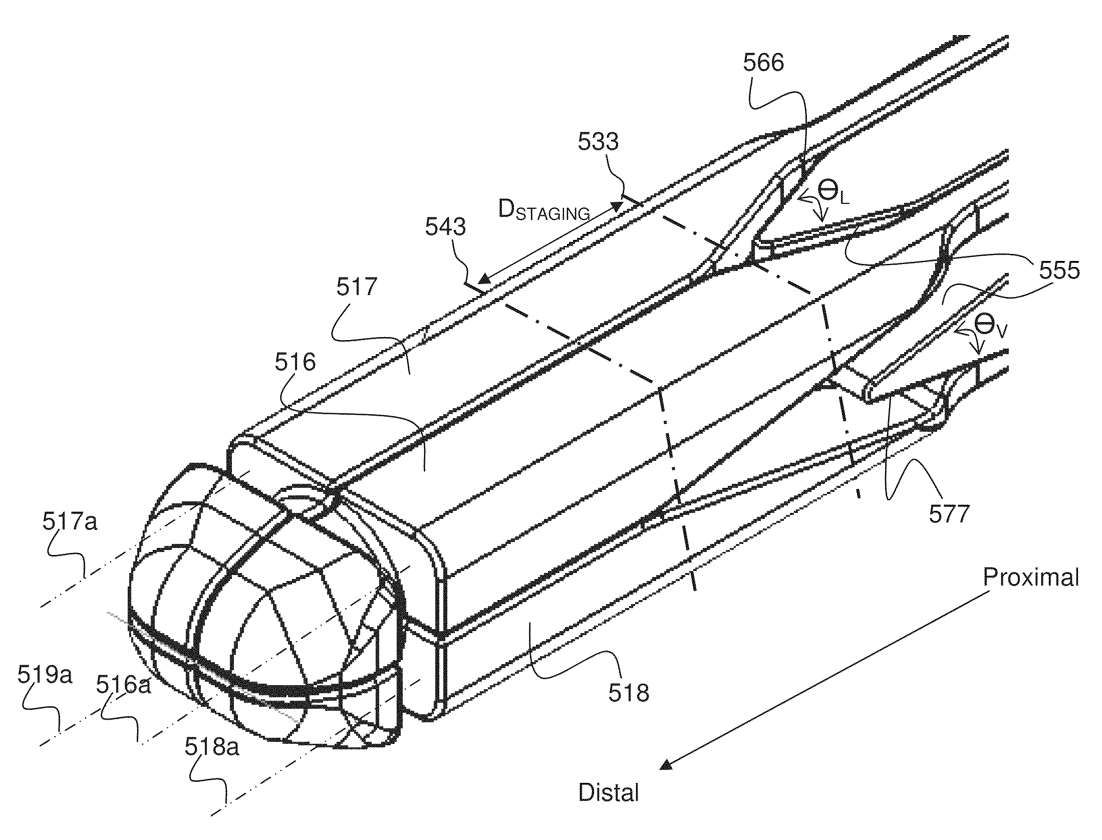
[0016]The head of the trial can have a collapsed dimension that facilitates insertion to the intervertebral space and an expanded dimension that facilitates the desired lateral expansion and vertical expansion in the intervertebral space. In some embodiments, the head of the trial can have a collapsed state with a transverse cross-section having a maximum dimension ranging from 5 mm to 18 mm for placing the frame in an intervertebral space through an annular opening for expansion in the intervertebral space. And, in some embodiments, the head of the trial can have an expanded state with a transverse cross-section having a maximum dimension ranging from 6.5 mm to 28 mm, 7.5 mm to 28 mm, 8.5 mm to 28 mm, 6.5 mm to 27 mm, 6.5 mm to 25 mm, 6.5 mm to 23 mm, 6.5 mm to 21 mm, 6.5 mm to 19 mm, 6.5 mm to 18 mm, or any range therein in increments of 1 mm, in the intervertebral space. In some embodiments, the shim can have a transverse cross-section with a maximum dimension ranging from 5 mm to 18 mm, 6 mm to 18 mm, 7 mm to 18 mm, 5 mm to 15 mm, 5 mm to 16 mm, 5 mm to 17 mm, or any range therein in increments of 1 mm, for translating the shim in the lumen of the shell.

Problems solved by technology

Unfortunately, therein lies a problem solved by the teachings provided herein.
Currently available systems can be problematic in that the methods of introducing the fusion cage and bone graft material creates “subsidence” of the cage into the adjoining vertebrae, resulting in a narrowing of the formerly distracted disc space.
This is because the cage is inserted near the middle of the endplate area which is softer than the areas at or near the peripheral zone of the endplate, and when it distracts, the cage actually sinks into the endplate creating the subsidence problem.
The problem remains with state-of-the-art distraction instruments, such as the Medtronic SCISSOR JACK, paddle trials, or oversized trial shims (metallic wedges).

Method used


Image

  • Staged, bilaterally expandable trial
  • Staged, bilaterally expandable trial
  • Staged, bilaterally expandable trial

Examples


Embodiment Construction

[0038]Systems and methods for distracting an intervertebral disc space using a staged, bilaterally expandable trial are provided. Generally speaking, a system for distracting an intervertebral disc space using a staged, bilaterally expandable trial is provided. Generally, the teachings are directed to a method of distracting an intervertebral space in a manner that addresses the problem of subsidence by selectively applying distraction forces to stronger portions of the vertebral endplates of the intervertebral space. It should be appreciated that the term “trial” can be used interchangeably with the term “distractor” in many embodiments.

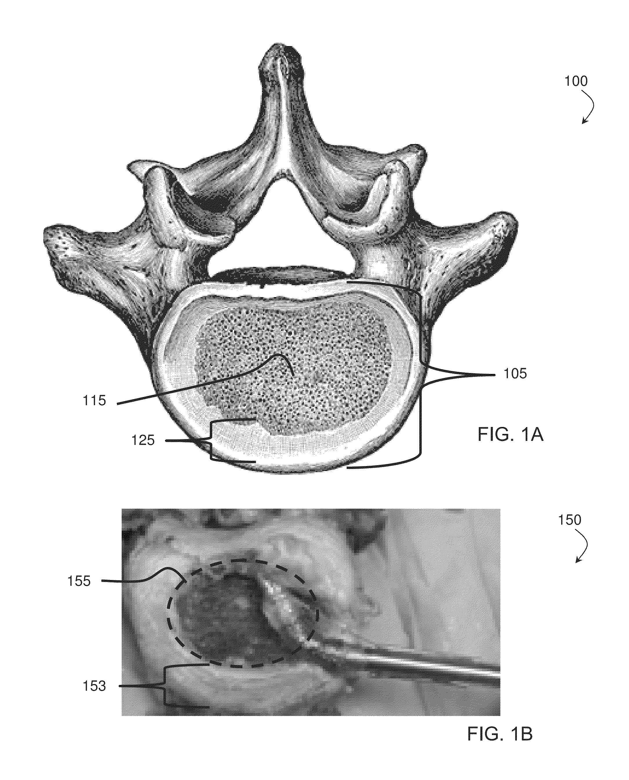
[0039]FIGS. 1A and 1B illustrate a sketch of an endplate of a vertebral body and a representative photograph of an intervertebral space using a cadaver intervertebral body and disc, according to some embodiments. This illustration provides a reference to discuss the state-of-the-art methods of introducing the fusion cage and bone graft material whic...


PUM


Abstract

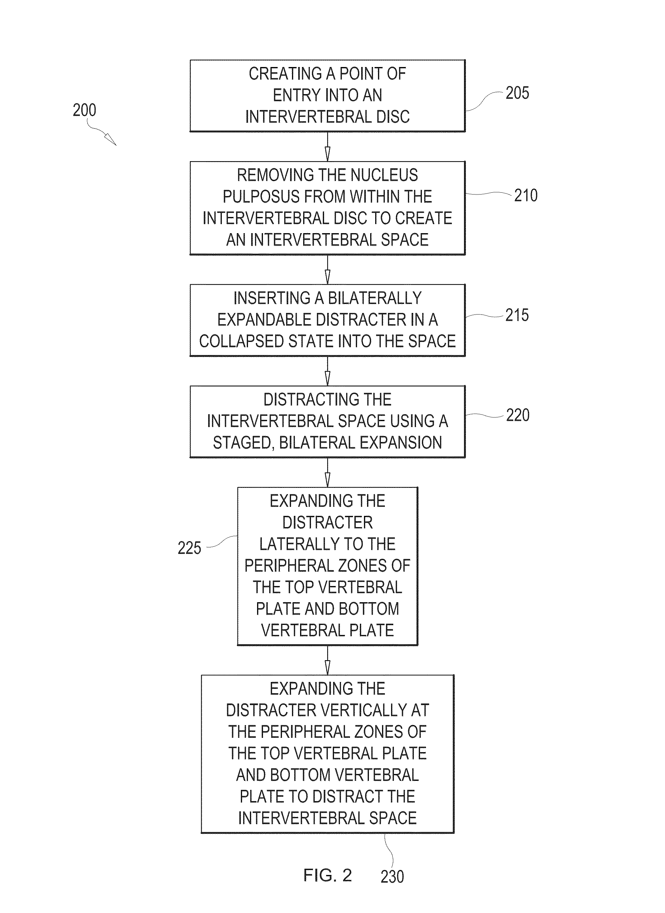
Systems and methods for distracting an intervertebral disc space are provided. The systems use a staged, bilaterally expandable trial. The systems and methods of distracting an intervertebral space are provided in a manner that addresses the problem of subsidence. The method includes inserting the trial into the intervertebral space in a collapsed state and, once inserted, the trial is then used for distracting the intervertebral space using an expansion that includes a first stage and a second stage. The first stage includes expanding the trial laterally toward the peripheral zones of the top vertebral plate and the bottom vertebral plate, and the second stage includes expanding the trial vertically to distract the intervertebral space.

Description

CROSS-REFERENCE TO RELATED APPLICATIONS[0001]This application claims the benefit of U.S. Application No. 61 / 875,688, filed Sep. 9, 2013, which is hereby incorporated herein by reference in its entirety.BACKGROUND[0002]1. Field of the Invention[0003]The teachings herein are directed to systems and methods for distracting an intervertebral disc space using a staged, bilaterally expandable trial.[0004]2. Description of the Related Art[0005]Bone grafts are used in spinal fusion, for example, which is a technique used to stabilize the spinal bones, or vertebrae, and a goal is to create a solid bridge of bone between two or more vertebrae. The fusion process includes “arthrodesis”, which can be thought of as the mending or welding together of two bones in a spinal joint space, much like a broken arm or leg healing in a cast. Spinal fusion may be recommended for a variety of conditions that might include, for example, a spondylolisthesis, a degenerative disc disease, a recurrent disc herni...

Claims


Application Information

Patent Timeline
Patent Type & Authority Patents(United States)
IPC IPC(8): A61F2/44A61B17/02
CPCA61F2/4425A61B17/025A61B2017/0256A61F2002/30266A61F2002/30545A61F2002/3055A61F2002/30556A61F2002/30563A61F2002/30565A61F2002/30579A61F2/4611A61F2/442A61F2/4684A61F2002/30179A61F2002/30014A61F2/4455A61F2002/30154
Inventor TO, JOHNRAO, PRAVEEN GOPAL
Owner INTEGRITY IMPLANTS INC
Why Eureka
Try Eureka