Head mounted display

a display and head technology, applied in the field of head mounted displays, can solve the problems of increasing the weight of the frame b>1010/b, and reducing the quality of the display, so as to minimize the effect of frame deformation and high quality and design

a display and head technology, applied in the field of head mounted displays, can solve the problems of increasing the weight of the frame b>1010/b, and reducing the quality of the display, so as to minimize the effect of frame deformation and high quality and design

US8988315B2Inactive Publication Date: 2015-03-24SONY CORP

Image

  • Head mounted display
  • Head mounted display
  • Head mounted display

Examples


first embodiment

Overall Structure of Head Mounted Display

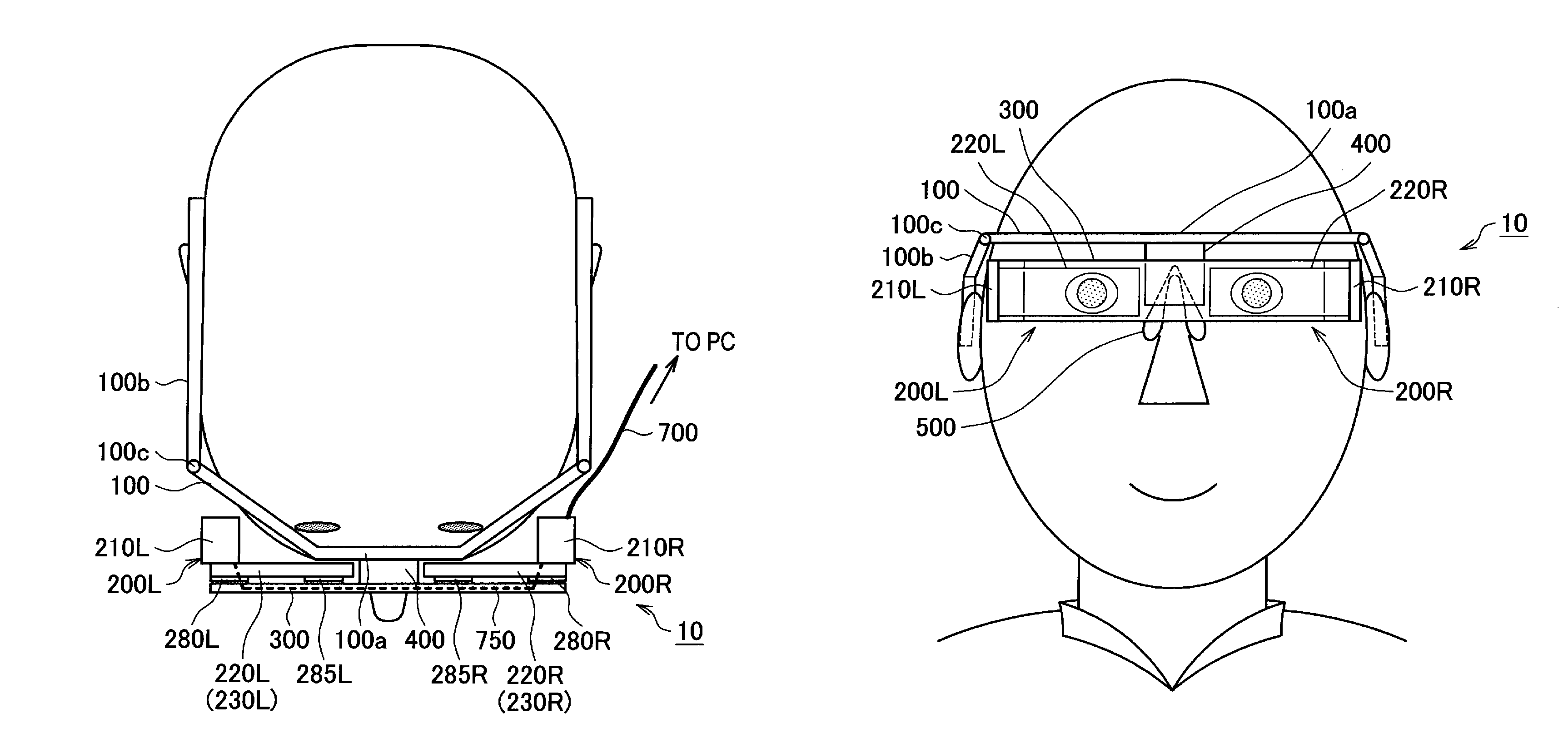
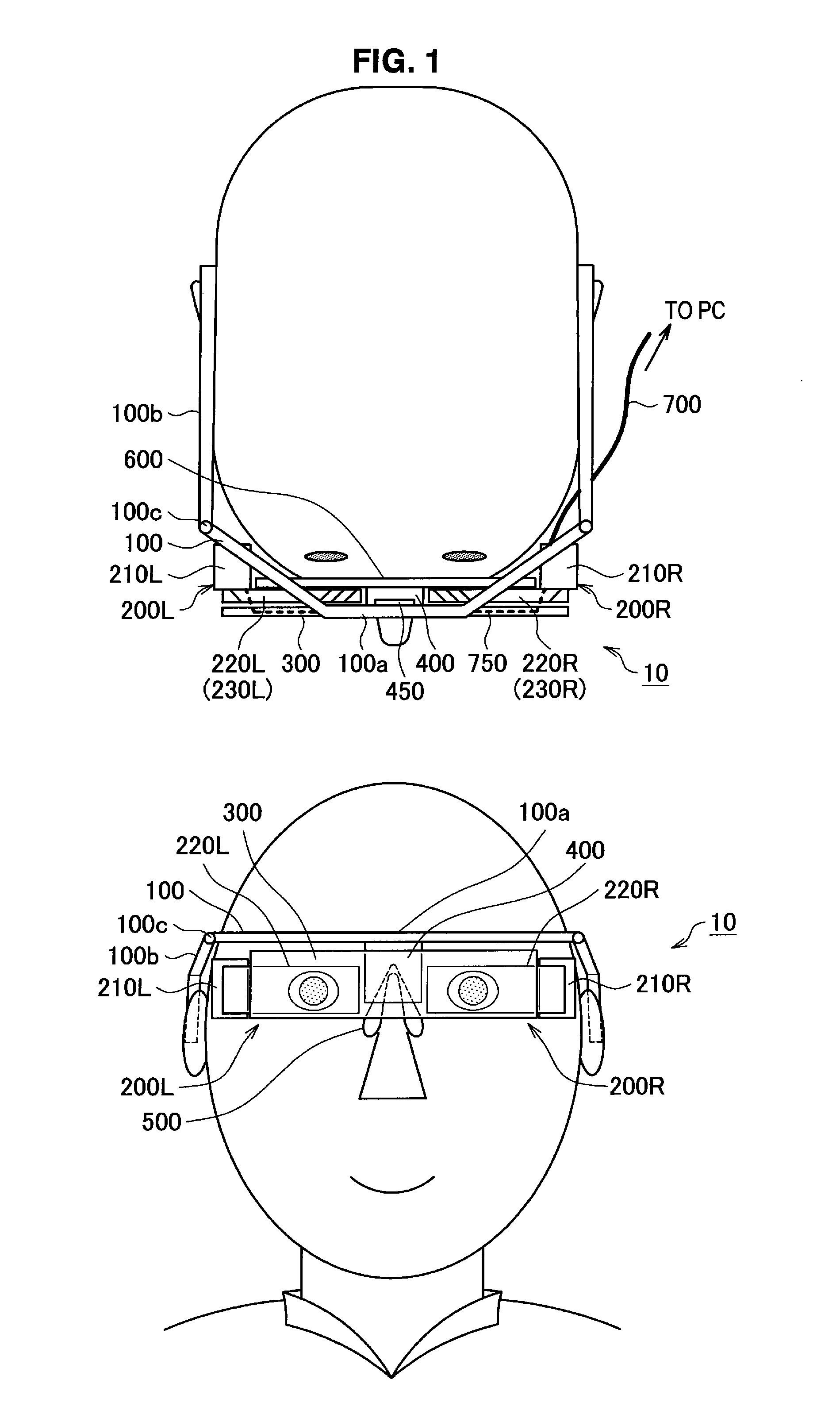
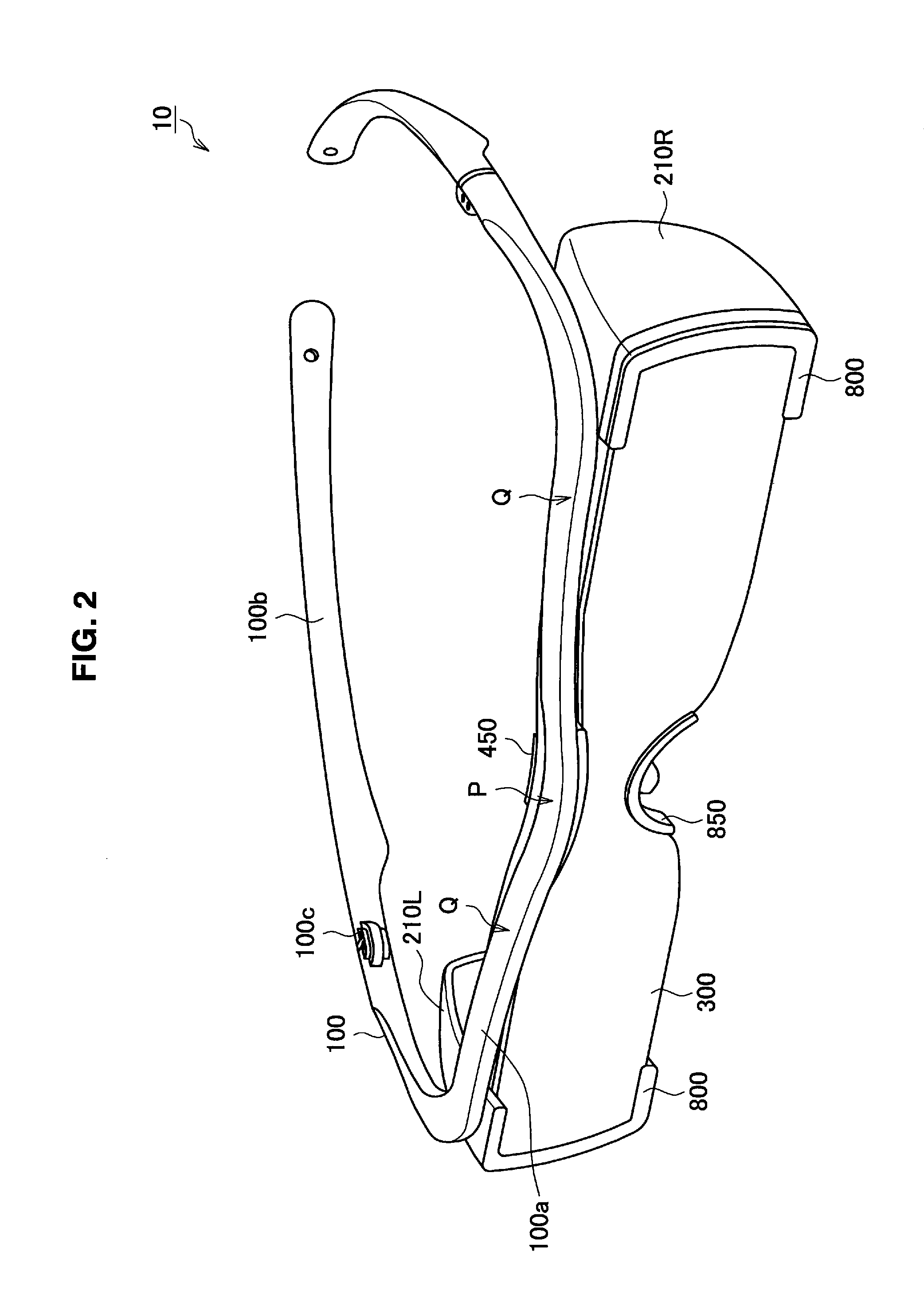
[0043]A head mounted display according to a first embodiment of the present invention is described hereinafter with reference to FIG. 1 as a conceptual illustration. At the bottom of FIG. 1 is a front view, and at the top is a plan view. A head mounted display 10 according to the embodiment includes a frame 100, optical modules 200L and 200R, an optical plate 300, a joint member 400, and a nose pad 500.

[0044]The frame 100 is a glasses-type frame to be worn on the head of an observer. The frame 100 is composed of a front part 100a placed at the front of an observer and two temples 100b rotatably attached to both ends of the front part 100a through a hinge 100c. The temples 100b are foldable toward the front part 100a with the hinge 100c as a supporting point.

[0045]The frame 100 according to the embodiment substantially has the same structure as normal glasses except that it does not have a rim. The material of the frame 100 is the same as the ...

second embodiment

Overall Structure of Head Mounted Display

[0086]An overall structure of a head mounted display according to a second embodiment of the present invention is described hereinafter. The second embodiment is an alternative example of the first embodiment. Referring to FIG. 5, the head mounted display 10 according to the second embodiment has a structure in which first polarizers 280L and 280R and second polarizers 285L and 285R are mounted on the surfaces of the light guide plates 220L and 220R, which is different from the structure of the head mounted display 10 according to the first embodiment in which the first polarizer 240 and the second polarizer 250 are formed in carved portions of the light guide plates 220L and 220R. The head mounted display 10 according to the second embodiment is described hereinafter mainly about such a difference.

[0087]As shown in the plan view of the head mounted display 10 at the top of FIG. 5, on the surfaces of the light guide plates 220L and 220R on th...


PUM


Abstract

There is provided a head mounted display including a glasses-type frame to be worn on a head of an observer; two optical modules including two image creation devices, and two light guides having two light guide plates coupled one-to-one with the two image creation devices and placed closer to a center of a face of the observer than the image creation devices are as a whole, that guide light beams output from the image creation devices and output the light beams toward pupils of the observer; and an optical plate supporting the two light guides, wherein the optical plate is attached to a center part of the frame.

Description

BACKGROUND OF THE INVENTION[0001]1. Field of the Invention[0002]The present invention relates to a head mounted display that is worn on the head of an observer and displays images (virtual images).[0003]2. Description of the Related Art[0004]A virtual image display device (image display device) that allows a user to observe a two-dimensional image formed by an image creation device as a magnified virtual image by a virtual image optical system is proposed today (cf. e.g. Japanese Unexamined Patent Application Publication No. 2006-162767).[0005]Further, in order for an observer to observe a two-dimensional image formed by an image creation device as a magnified virtual image by a virtual image optical system, a head mounted image display device using a holographic diffraction grating is also proposed (cf. e.g. Japanese Unexamined Patent Application Publication No. 2007-94175).[0006]FIG. 14 shows a state where an observer is wearing a glasses-type image display device 90. At the left ...

Claims


Application Information

Patent Timeline
24 Mar 2015
Publication
US8988315B2
IPC
G09G5/00; G02B5/32; G02B6/00; G02B27/01
CPC
G02B5/32; G02B27/0172; G02B6/00; G02B2027/0134; G02B2027/0174
Inventors
MUKAWA, HIROSHI; KAGAWA, ATSUSHI