Dental scanner device and system and methods of use

a scanner and dental technology, applied in the field of dental scanners, can solve the problems of significant challenges in the intraoral cavity, slow and costly process, and inconvenient use, and achieve the effects of saving time, cost, and reducing discomfort for patients

Active Publication Date: 2015-03-24
CARNOJAAL
View PDF7 Cites 26 Cited by
  • Summary
  • Abstract
  • Description
  • Claims
  • Application Information

AI Technical Summary

Benefits of technology

[0013]The housing body of the device contains or encases a chassis providing a mobility mechanism for moving, guiding, or directing a scanning probe coupled to the mobility mechanism. By providing a mobility mechanism for operating the movement of the scanning probe in a fixed or pre-programmed pattern relative to the mouthpiece, the device and its use can advantageously provide a fixed reference point for the scanning probe, obviating the need for a hand-manipulated wand.
[0043]Advantageously, the scanning device of the subject invention can provide a method for scanning teeth and gingivae without the need for imaging powder or imaging gel applied or administered to the teeth or gingivae of the patient or subject. Thus the subject method can be a powder-free or gel-free scanning procedure, which can save time, cost, and reduce discomfort to the patient or subject.

Problems solved by technology

However, these mainstream techniques pose problems and disadvantages which are manifold.
These problems include: patient discomfort during the process of creating the mold, creation of imperfections and inaccuracies in the resulting mold, and the process can be slow and costly.
These systems and devices previously described all have various disadvantages in their design and use in practice.
The intraoral cavity represents a significant challenge for accurate in vivo 3D imaging of the surface of teeth and tissue.
Further, linear or rotational motion adds to error accumulation and the variation in size and curvature of human jaws makes a “one size fits all” scanner problematic.
In addition to the inaccuracies that can be introduced, these state-of-the-art devices and systems can be inconvenient to use, and inconvenient for the patient.
Systems based on photographs taken by the various devices where software interprets and interpolates the photographic information into a final 3D image, can be time-consuming.

Method used


Image

  • Dental scanner device and system and methods of use
  • Dental scanner device and system and methods of use
  • Dental scanner device and system and methods of use

Examples


Embodiment Construction

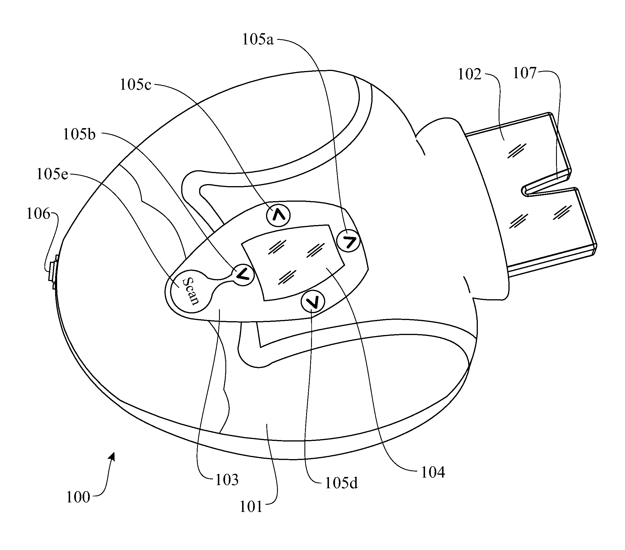
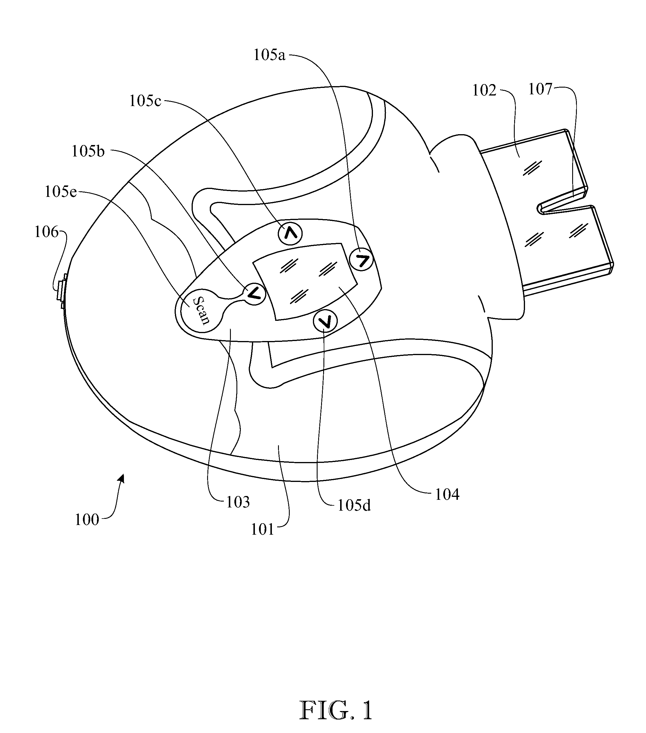
[0052]To describe and illustrate the components of a device of the invention, reference is made to the accompanying drawings, whereby: FIG. 1 shows an embodiment of a device 100 according to the subject invention, illustrating a top or bottom view of the housing body 101 and mouthpiece 102 in an engaged configuration. Reference is made to “either” the top face or bottom face of the device because, in a preferred embodiment, the device is symmetrical wherein the top and bottom faces are identical or at least substantially identical so that the device can be operated in an identical or substantially identical manner when facing upward or downward.

[0053]During operation, the device is positioned, for example, upwardly to perform a scan of an upper dental arch, and the device may then be rotated approximately 180° to face downward for scanning, for example, the lower dental arch. In both instances, a control panel 103 provided on each top and bottom face, provides for easy access and ma...


PUM

PropertyMeasurementUnit
surface contouraaaaaaaaaa
Optical Probeaaaaaaaaaa
Three Dimensional Structureaaaaaaaaaa

Abstract

A three-dimensional (3D) scanner device for generating a three dimensional (3D) surface model of shaped objects, such as dental structures, applicable for use in the field of dentistry, particularly to dental prosthetics manufacturing. Methods and systems relating to the device are also disclosed.

Description

BACKGROUND OF THE INVENTION[0001]The subject invention relates to a scanner device for generating a three dimensional (3D) surface model of arbitrarily shaped objects, such as dental structures, preferably applicable for use in the field of stomatology, dentistry, or orthodontics, and particularly to dental prosthetics manufacturing. More specifically, the subject invention includes an intraoral 3D dental scanning device and methods for imaging and visualizing teeth or gingivae surfaces, including the conformation thereof.[0002]Three-dimensional (3D) diagnostic and therapeutic modeling of teeth and gingivae have been traditionally obtained by mainstream techniques, such as using replicas obtained from alginate-impressed molds. Such replicas provide gingiva and tooth negative-image molds, which can later be converted into positive models, which may be scanned. However, these mainstream techniques pose problems and disadvantages which are manifold. These problems include: patient disc...

Claims


Application Information

Patent Timeline
Patent Type & Authority Patents(United States)
IPC IPC(8): A61B1/05A61B1/00A61C1/08A61C5/14A61C9/00A61C13/00
CPCA61C9/0053A61C5/14A61C13/0004A61C13/0019A61C1/088A61B1/05A61B1/00147A61B1/24Y10T29/49567A61B1/00172G16H20/40A61B1/247
Inventor PULIDO, ALFONSO FERNANDEZGARCIA, DAVID DE PABLOS
Owner CARNOJAAL
Why Eureka
Try Eureka