
Personnel screening system

a screening system and personnel technology, applied in the field of security systems, can solve the problems of inconvenient portability, difficult and time-consuming use and/or transportation, and the size of the security system is presently limited in the ability to detect contraband, weapons, explosives, and other dangerous objects hidden under clothing. the effect of reducing the required footprint of the system

Active Publication Date: 2015-03-31
RAPISCAN SYST INC (US)
View PDF280 Cites 24 Cited by
  • Summary
  • Abstract
  • Description
  • Claims
  • Application Information

AI Technical Summary

Benefits of technology

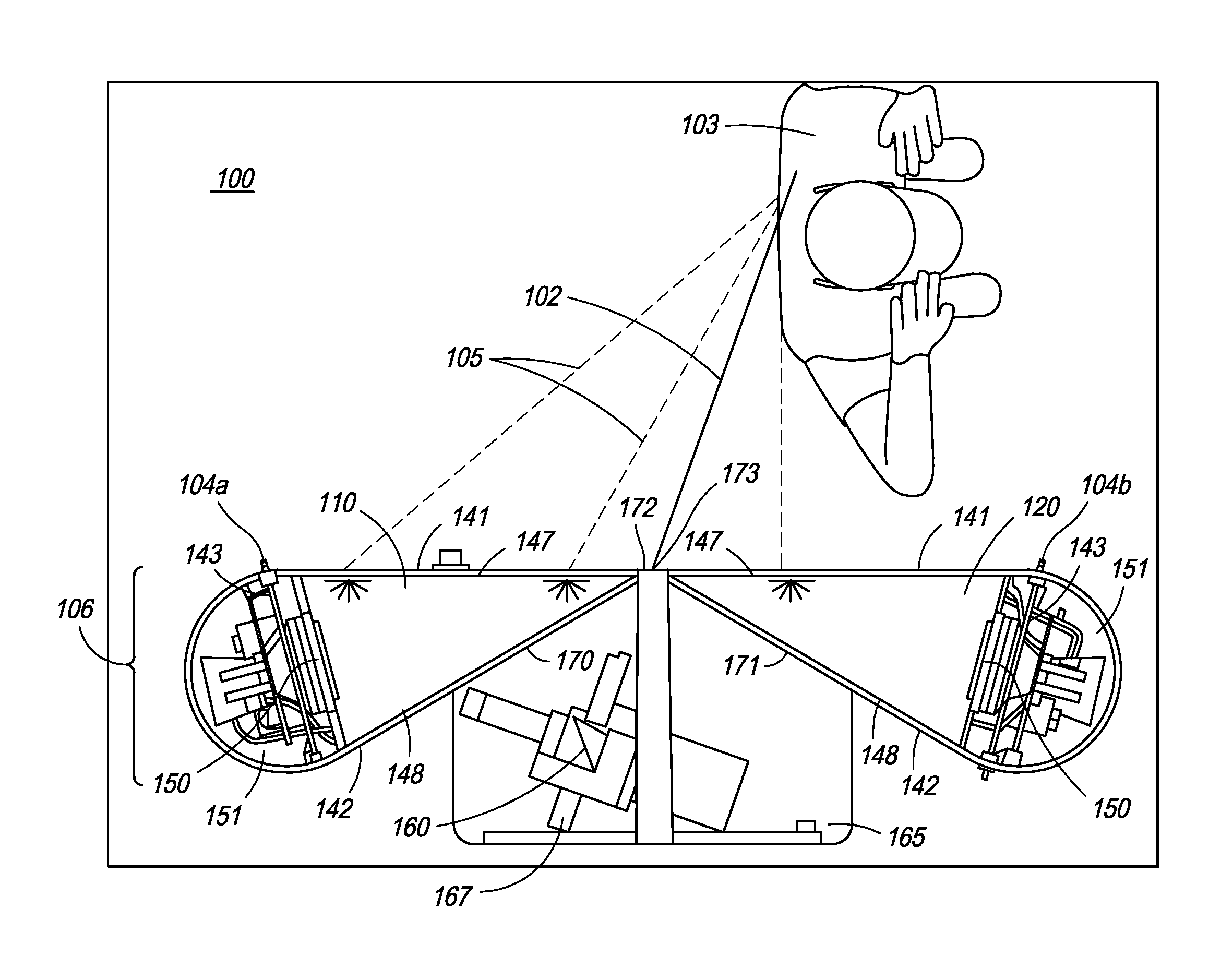
[0023]As further discussed below, the system can be configured with two systems opposing each other and defining a pathway for a person to walk through and an inspection volume. In one embodiment, the detection system and X-ray system enclosures are configured with hinged doors which open into the inspection volume and which do not open behind the systems, thereby decreasing the required footprint of the systems.

Problems solved by technology

Radiation based systems for screening people and in use today at transit points, such as airports, courthouses, etc., are generally portal systems that are bulky and not conducive for portable applications.
Unfortunately, such prior art screening systems are not compact enough (example, have heavy back-end cables and wires for connecting the photomultiplier tubes to a centralized analog-to-digital conversion and power station) and are often difficult and time-consuming to use and / or transport.
Also, security systems are presently limited in their ability to detect contraband, weapons, explosives, and other dangerous objects concealed under clothing.
Metal detectors and chemical sniffers are commonly used for the detection of large metal objects and certain types of explosives, however, a wide range of dangerous objects exist that cannot be detected using these devices.
Manual searching of subjects is slow, is inconvenient, and would not be well tolerated by the general public, especially as a standard procedure in high traffic centers, such as at airports.
Known prior art X-ray systems for detecting objects concealed on persons have limitations in their design and method that prohibit them from achieving low radiation doses, which is a health requirement, or prevent the generation of high image quality, which are prerequisites for commercial acceptance.
An inspection system that operates at a low level of radiation exposure is limited in its precision by the small amount of radiation that can be directed towards a person being searched.
X-ray absorption and scattering further reduces the amount of X-rays available to form an image of the person and any concealed objects.
In prior art systems this low number of detected X-rays has resulted in unacceptably poor image quality.
This problem is even more significant if an X-ray inspection system is being used in open venues such as stadiums, shopping malls, open-air exhibitions and fairs, etc.
If a person being scanned is not very close to the X-ray machine, the resultant image may not be clear enough since the amount of radiation reaching the person is very low.
This limits the range of scanning of the system to a few feet from the front of the machine.
If, however, a person being scanned is too close to the X-ray machine, the amount of radiation impinging on the person may not be safe.

Method used


Image

  • Personnel screening system
  • Personnel screening system
  • Personnel screening system

Examples


Embodiment Construction

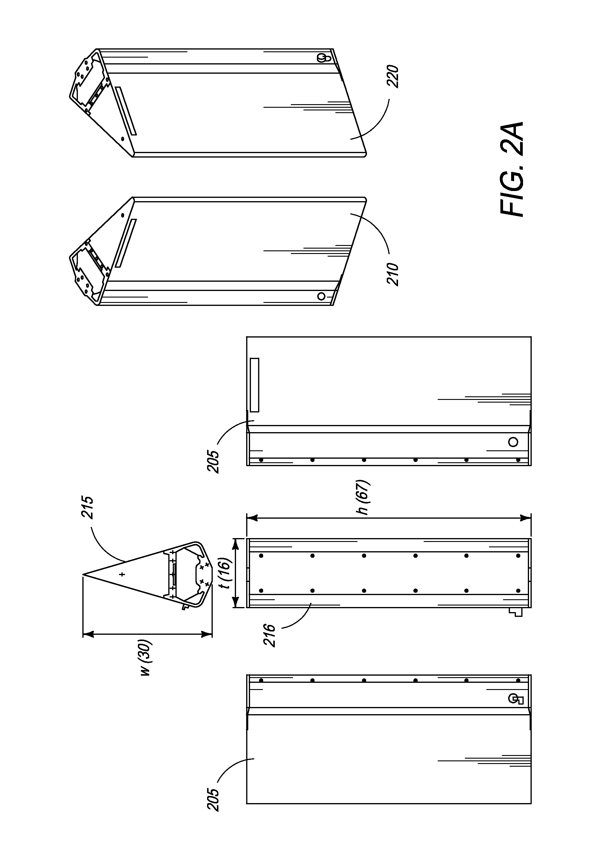
[0061]The present specification is directed towards personnel screening systems comprising modular components, including detector and source units. The modular components of the present invention allow for compact, light and yet sufficiently rugged overall structure that can be disassembled for ease of transportation and is also simple to reassemble at a required site for inspection. The novel modular architecture of the screening system of the present invention also allows for the modular components to be fabricated separately and be quickly snapped on for assembly. Similarly, the modular components can be easily disassembled for ease of service access to the selective components and / or for packaging for subsequent transportation.

[0062]The present specification is also an improved method for screening individuals at security locations without exposing individuals to high radiation and retaining the efficiency of the screening process. The disclosed system allows for maximum threat ...


PUM

PropertyMeasurementUnit
diameteraaaaaaaaaa
diameteraaaaaaaaaa
decay timeaaaaaaaaaa

Abstract

The present specification discloses an inspection system for detecting objects being carried by a person who is moving along a pathway. The inspection system has two detection systems configured to detect radiation scattered from the person as the person moves along the pathway and an X-ray source positioned between the detection systems. The X-ray source is configured to generate a vertical beam spot pattern and does not generate beams that move horizontally.

Description

CROSS-REFERENCE TO RELATED APPLICATIONS[0001]The present application relies on U.S. Provisional Patent Application No. 61 / 313,772, filed on Mar. 14, 2010, for priority, which is herein incorporated by reference in its entirety.[0002]The present application also relies on U.S. Provisional Patent Application No. 61 / 423,585, filed on Dec. 15, 2010, for priority, which is herein incorporated by reference in its entirety.[0003]In addition, the present application relies on U.S. Provisional Patent Application No. 61 / 423,582, filed on Dec. 15, 2010, for priority, which is herein incorporated by reference in its entirety.[0004]In addition, the present application relies on U.S. Provisional Patent Application No. 61 / 423,586, filed on Dec. 15, 2010, for priority, which is herein incorporated by reference in its entirety.[0005]Further, the present application is a continuation-in-part of U.S. patent application Ser. No. 12 / 887,510, entitled “Security System for Screening People” and assigned t...

Claims


Application Information

Patent Timeline
Patent Type & Authority Patents(United States)
IPC IPC(8): G01N23/201G01V5/00
CPCG01V5/0008G01V5/0025
Inventor GRAY, STEPHENHUGHES, RONALDRYGE, PETERKOTOWSKI, ANDREAS F.
Owner RAPISCAN SYST INC (US)
Learn More