Lid and container provided therewith

a technology for a container and a lid, which is applied in the field of lids and containers, can solve the problems of increasing the number of components, the container cannot be sealed, and the air hole is not easy to adhere the projection to the air hole precisely, so as to achieve the effect of enhancing the adhesion between the projection and the inner wall surface of the air hol

Active Publication Date: 2015-04-07
IWASAKI IND
View PDF9 Cites 6 Cited by
  • Summary
  • Abstract
  • Description
  • Claims
  • Application Information

AI Technical Summary

Benefits of technology

[0006]According to this configuration, when the flap travels from the second position to the first position, the projection comes into contact with the circumferential edge of the opening of the air hole on the side opposite the hinge, and then the projection fits in the air hole as the flap elastically deforms. Therefore, the projection can be fitted in the air hole while elastic force acts thereon. It is thus possible to enhance adhesion between the air hole and the projection. In particular, the air hole and the projection aligned as described above are advantageous in that adhesion that takes advantage of elastic force can be obtained in addition to adhesion that is attained by adjusting the outer diameter of the air hole and the inner diameter of the projection. Note that the elastic deformation of the flap herein means that elastic deformation occurs in any portion of the flap. That is, the projection may be configured to fit in the air hole due to the deflection of at least one of the base, hinge, and projection. The second position of the flap is not particularly limited and refers to any state in which the projection is detached from the air hole, and the flap may be at any angle within the extent of swinging of the flap. The phrase “tip of the projection” encompasses the tip surface and a portion around the tip surface, and also the phrase “circumferential edge part of the opening of the air hole” encompasses the circumferential edge of the opening and the inner wall of the opening.
[0007]For example, the projection can be formed such that the diameter becomes smaller from the flap toward the tip side. Accordingly, the space between the projection and the air hole decreases as the projection enters the air hole, and the projection can fit in the air hole eventually without any space therebetween. Thus, the projection easily enters the air hole, and a dimensional error is cancelled, thus making it possible to enhance adhesion.
[0008]The lid may be configured such that the flap is further provided with a first latch that is attached to the second end side of the base, the body part is further provided with a second latching part that can engage with a portion of the first latching part facing the hinge side, and the first latching part and the second latching part engage when the flap is in the first position. Accordingly, the first latching part and the second latching part engage when the flap is in the first position, thus making it possible to retain the flap in the first position and prevent the projection from being unintentionally detached from the air hole. When the flap travels from the second position to the first position, the projection moves toward the hinge side, accompanying elastic deformation of the flap, and thus the base of the flap is pulled toward the hinge side. At this time, since the second latch and the portion of the first latching part facing the hinge side are engaged, the base that is being pulled causes the latching parts to be more tightly engaged. As a result, the latching parts reach a firmly engaged state, thus making it possible to more strongly retain the flap in the first position.
[0009]The flap may be further provided with at least one first rib that extends from the first end side toward the second end side of the base. This configuration provides the following advantages. Generally, resin molding may result in a warped product. Alignment of the projection and the air hole is important in the present invention, and for example, a warped flap can result in the problem that the relative positions of the projection and the air hole do not match, and the projection does not come into contact with the circumferential edge of the opening of the air hole before the flap reaches the first position. Accordingly, providing the base of the flap with a first rib as described above makes it possible to prevent warpage of the flap. As a result, the projection and the air hole can be precisely aligned.
[0010]In the lid, the second end side of the base of the flap may be rounded, and the base may be provided with a second rib that extends in a second direction that is perpendicular to a first direction extending from the first end toward the second end, at a predetermined distance away from the second end toward the first end side. Providing such a rib can reinforce the flap and prevents warpage. Also, disposing the second rib at a predetermined distance away from the rounded end of the base makes it possible to prevent the second rib from becoming obstructive when lifting the flap upright by placing the fingers on the second end of the base.
[0012]According to the present invention, adhesion between the projection and the inner wall surface of the air hole can be enhanced.

Problems solved by technology

Meanwhile, attachment of a circular gasket to the projection as described above is problematic in that it results in an increased number of components although the adhesion between the projection and the air hole is enhanced.
In addition, it is also problematic in that the container cannot be sealed if the gasket is detached and lost.
However, it is not easy to precisely adhere the projection to the air hole if the flap and the lid are integrally formed.
For example, if adhesion is poor, not only can the container not be sealed but also the projection may be easily detached from the air hole.

Method used


Image

  • Lid and container provided therewith
  • Lid and container provided therewith
  • Lid and container provided therewith

Examples


Embodiment Construction

[0024]Below, an embodiment of the present invention applied to a lid and an airtight container for accommodating food will now be described with reference to the drawings. Note that in the description below, the right-left direction of FIG. 4 will be referred to as the width direction, and the top-bottom direction will be referred to as the longitudinal direction. Also, the upper side of FIG. 4 is referred to as a first end (one end) side, and the lower side is referred to as a second end (the other end) side. These apply to the other drawings as well.

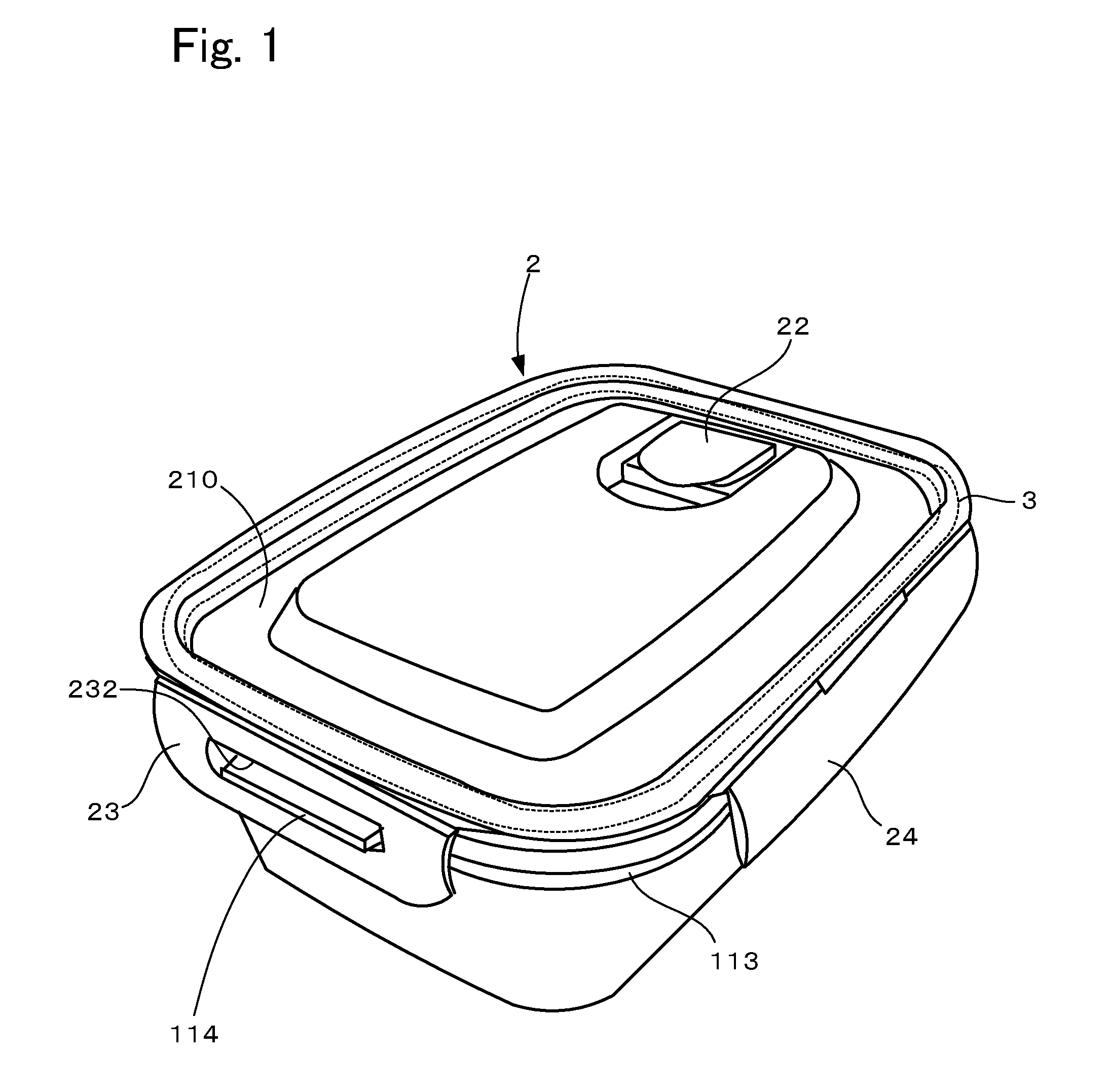
[0025]FIG. 1 is a perspective view of a container according to one embodiment. As shown in FIG. 1, the container of this embodiment is configured with a container body 1 that has an opening in the upper part, a lid 2 that covers the opening in the upper part of the container body 1, and a sealing member 3 for fixing the container body 1 and the lid 2 so as to be liquid-tight. Below, these components will now be described in detail.

[002...


PUM


Abstract

A resin lid for a container body with an opening in an upper part, including a body part that closes the opening and has an air hole, and a flap that includes a base, a hinge on a first end of the base, and a projection provided on a second end side of the base and fitted in the air hole. The flap is swingable around the hinge between a first position in which the projection fits in the air hole and a second position in which the air hole is open. The body part and flap are integrally formed. When the flap travels from the second to the first position, a tip of the projection comes into contact with a circumferential edge of the opening of the air hole on a side opposite the hinge, and the projection fits in the air hole as the flap elastically deforms.

Description

FIELD OF THE INVENTION[0001]The present invention relates to a lid and a container provided with the lid.BACKGROUND OF THE INVENTION[0002]Heretofore, various containers for sealing food have been proposed. For example, JP 2004-113776A discloses a container that includes a container body having an opening in the upper part and a lid attached to the container body for sealing. The lid of this container is provided with a swingable flap, and the container is configured to be capable of opening or closing the air hole formed in the lid by the flap. More specifically, the projection provided on the lower surface of the flap is fitted in the air hole to attain an airtight state, and the flap is lifted upright to remove the projection from the air hole, thus making it possible to introduce air into the container. Accordingly, closing the air hole by the flap makes it possible to seal the container, and on the other hand, operating the flap to open the air hole makes it possible to, for exa...

Claims


Application Information

Patent Timeline
Patent Type & Authority Patents(United States)
IPC IPC(8): B65D51/18B65D51/16B65D43/14A45C11/20A45C13/00B65D45/22
CPCB65D51/1683A45C11/20B65D45/22A45C13/008B65D81/3446
Inventor IWASAKI, YOSHIHISA
Owner IWASAKI IND
Why Eureka
Try Eureka