Film depositing apparatus

a film and film technology, applied in chemical vapor deposition coatings, metal material coating processes, coatings, etc., can solve problems such as inability to produce films with uniform thickness distribution, and achieve high uniform thickness

Inactive Publication Date: 2015-04-07
FUJIFILM CORP
View PDF13 Cites 0 Cited by
  • Summary
  • Abstract
  • Description
  • Claims
  • Application Information

AI Technical Summary

Benefits of technology

[0009]An object, therefore, of the present invention is to solve the aforementioned problem of the prior art by providing a film depositing apparatus which, when forming a film continuously on an elongated substrate as it is transported, is capable of forming a film having high uniformity in thickness in the direction of width of the substrate that is perpendicular to its longitudinal direction.

Problems solved by technology

Hence, the plasma-enhanced CVD apparatus disclosed in JP 2006-152416 A, which does not take into account the direction in which the reactive gases are to be discharged, has the problem that it is unable to produce films having a uniform thickness distribution.

Method used


Image

  • Film depositing apparatus
  • Film depositing apparatus
  • Film depositing apparatus

Examples


Embodiment Construction

[0013]On the following pages, the film depositing apparatus of the present invention is described in detail with reference to the preferred embodiment shown in the accompanying drawings.

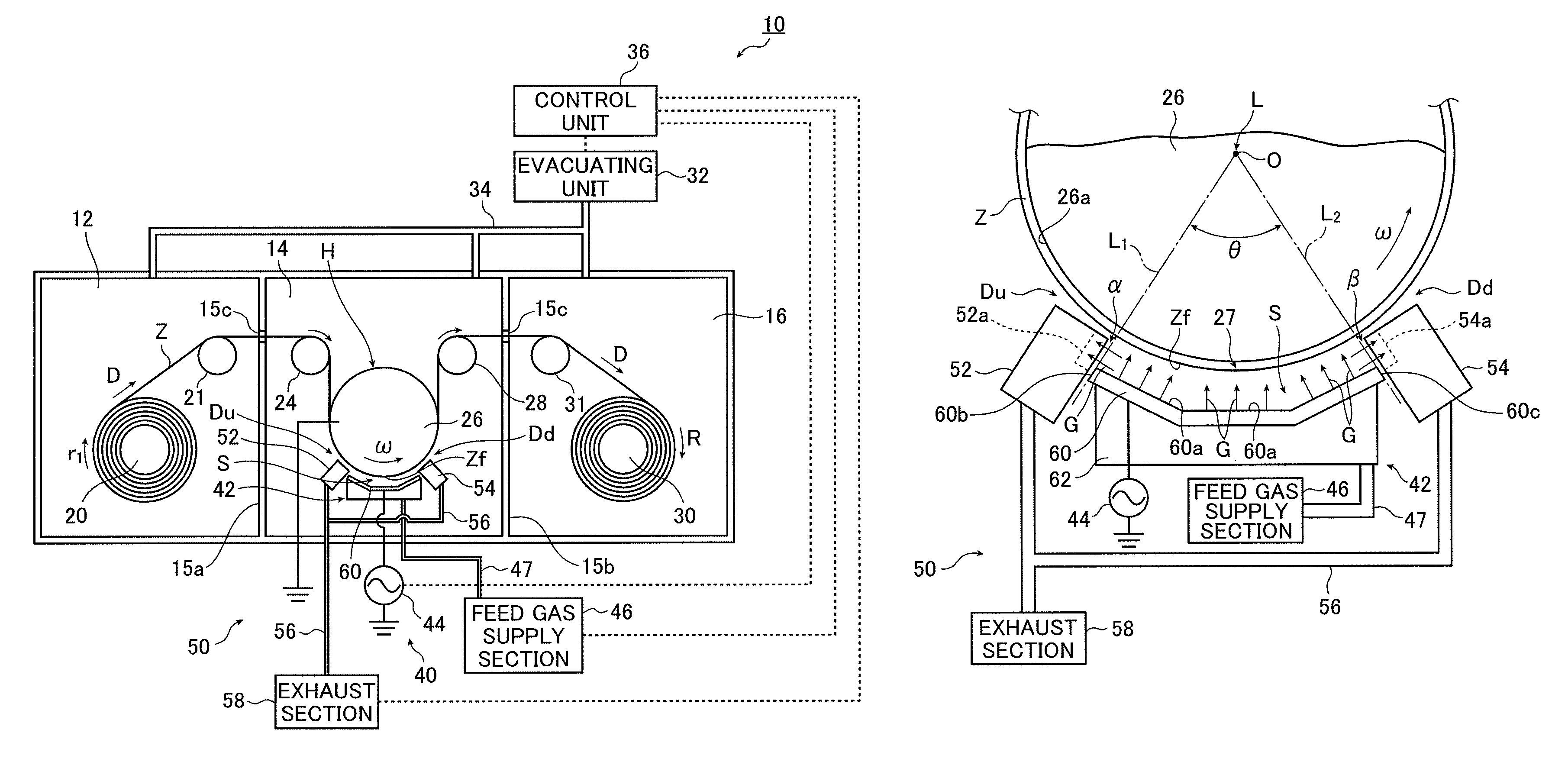
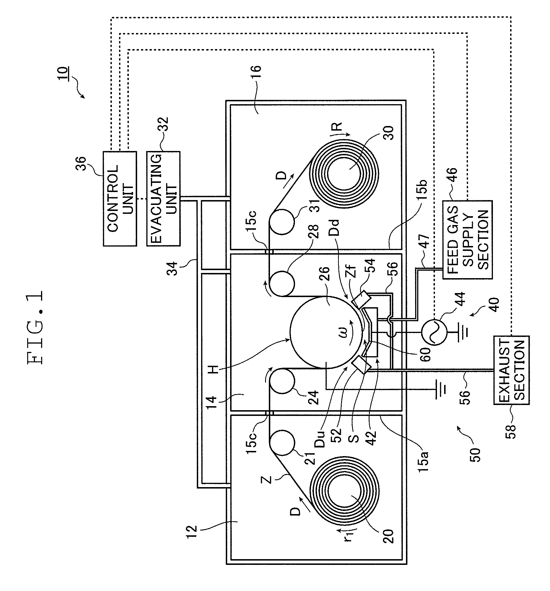
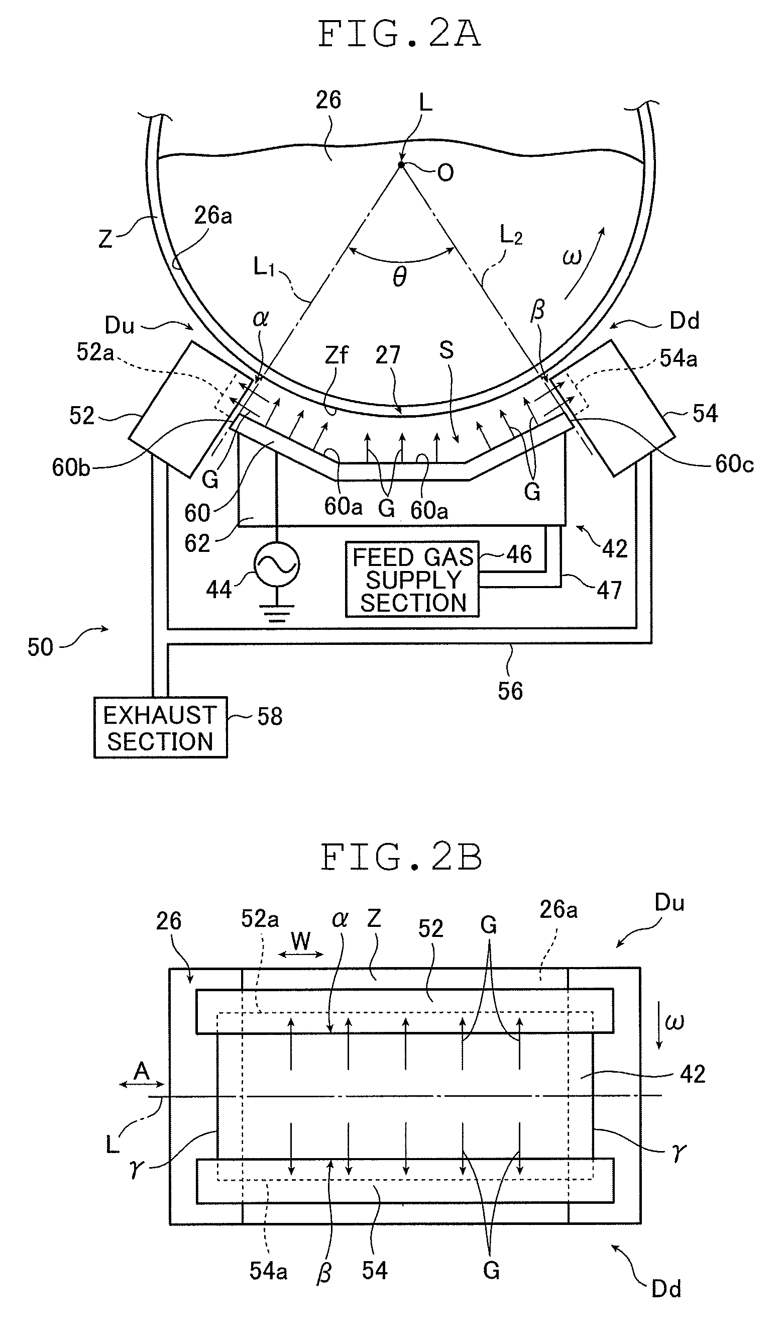
[0014]FIG. 1 is a schematic diagram showing a film depositing apparatus according to an embodiment of the present invention. FIG. 2A is a schematic side view showing the relative positions of a drum, a film depositing electrode and an exhaust means in a film depositing compartment of the film depositing apparatus shown in FIG. 1. FIG. 2B is a schematic plan view showing the relative positions of the drum, the film depositing electrode and exhaust boxes in the film depositing compartment of the film depositing apparatus shown in FIG. 1.

[0015]The film depositing apparatus generally indicated by 10 in FIG. 1 according to the embodiment under consideration is a roll-to-roll type machine that forms a film with a specified function on the surface Zf of a substrate Z or on the surface of an organic layer if...


PUM

PropertyMeasurementUnit
degree of vacuumaaaaaaaaaa
axis of rotationaaaaaaaaaa
distanceaaaaaaaaaa

Abstract

A film depositing apparatus comprises: a rotatable drum within a chamber around which a substrate is wrapped in a specified surface region; a film depositing unit comprising a film depositing electrode spaced facing to a surface of the drum, and a feed gas supply section supplying a feed gas for forming a film into a gap between the drum and the film depositing electrode; and an exhaust unit that exhausts the gap between the drum and the film depositing electrode during film formation by the film depositing unit so as to forcibly discharge the feed gas, supplied into the gap by the feed gas supply section, through at least one of end portions of the gap upstream side and downstream side in a rotating direction of the drum uniformly over an entire region of the gap in a direction parallel to the axis of rotation of the drum.

Description

[0001]The entire contents of a document cited in this specification are incorporated herein by reference.BACKGROUND OF THE INVENTION[0002]The present invention relates to a film depositing apparatus for forming a film on a surface of an elongated substrate in vacuum by CVD and, more particularly, to a film depositing apparatus which, when forming a film continuously on the elongated substrate as it is transported, is capable of forming a film having high uniformity in thickness in the direction of width of the substrate that is perpendicular to its longitudinal direction.[0003]While various types of apparatus are known to be capable of continuous film deposition on an elongated substrate (a web of substrate) in a vacuum-filled chamber by plasma-enhanced CVD, an exemplary system uses a drum electrically connected to the ground and an electrode positioned in a face-to-face relationship with the drum and connected to a radio-frequency power source.[0004]In this type of film depositing ...

Claims


Application Information

Patent Timeline
Patent Type & Authority Patents(United States)
IPC IPC(8): C23C16/503C23C16/54C23C16/44C23C16/455C23C16/509
CPCC23C16/509C23C16/4412C23C16/45502C23C16/545
Inventor FUJINAMI, TATSUYATAKAHASHI, TOSHIYA
Owner FUJIFILM CORP
Why Eureka
Try Eureka