Plating apparatus and plating method

Inactive Publication Date: 2007-04-17
DAINIPPON SCREEN MTG CO LTD
View PDF12 Cites 0 Cited by
  • Summary
  • Abstract
  • Description
  • Claims
  • Application Information

AI Technical Summary

Benefits of technology

[0059]The substrate may have a generally round shape, and the tubular interior surface may be a cylindrical interior surface having an inner diameter which is nearly equal to the diameter of the generall

Problems solved by technology

That is, the resistance of the first path is increased as compared with the re

Method used


Image

  • Plating apparatus and plating method
  • Plating apparatus and plating method
  • Plating apparatus and plating method

Examples


Embodiment Construction

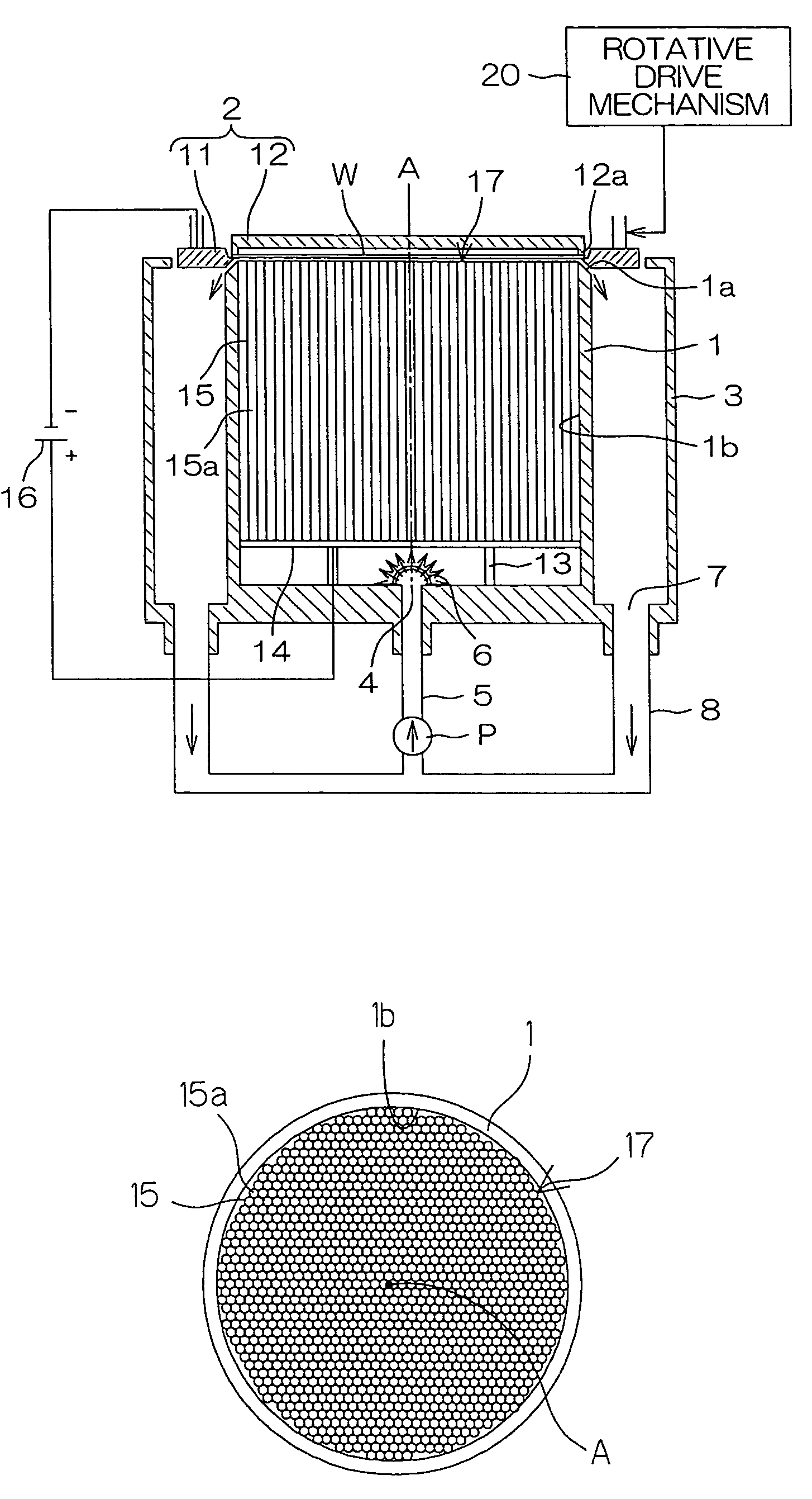
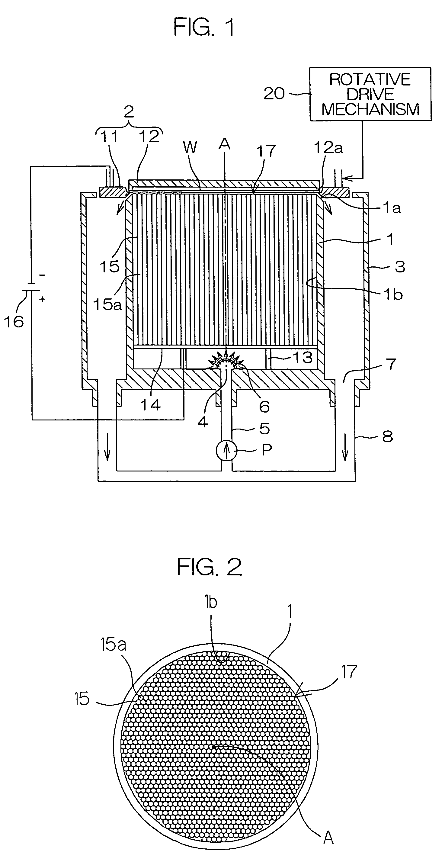
[0065]FIG. 1 is a schematic sectional view illustrating the construction of a plating apparatus according to one embodiment of the present invention.

[0066]The plating apparatus is adapted to perform a plating process for copper-plating one surface of a semiconductor substrate W as a generally round substrate (hereinafter referred to as “wafer”), and includes a plating vessel 1 for containing a plating liquid, and a holder 2 for generally horizontally holding the wafer W above the plating vessel 1.

[0067]The holder 2 includes a cathode ring 11 having a ring-shape as seen in plan and including a plurality of cathodes (not shown), and a disk-shaped press member 12. The cathode ring 11 has an inner diameter slightly smaller than the diameter of the wafer W. The press member 12 has substantially the same diameter as the wafer W, and includes an annular projection 12a provided circumferentially of the press member 12 on one surface of the press member 12 (in opposed relation to the wafer. ...


PUM

PropertyMeasurementUnit
Areaaaaaaaaaaa
Diameteraaaaaaaaaa
Areaaaaaaaaaaa

Abstract

A plating apparatus for performing a plating process for plating a surface of a substrate. This plating apparatus is provided with a first electrode to be brought into contact with a peripheral edge portion of the substrate; a plating vessel for containing a plating liquid to be brought into contact with the surface of the substrate, the plating vessel having a vertical tubular interior surface; a second electrode disposed in the plating vessel, the second electrode being spaced from the substrate by a distance which is not smaller than a distance between a center portion and a peripheral edge portion of the substrate during the plating process; and an electric current limiting member for limiting horizontal flow of an electric current in the plating liquid between the second electrode and the substrate within the plating vessel during the plating process.

Description

BACKGROUND OF THE INVENTION[0001]1. Field of the Invention[0002]The present invention relates to a plating apparatus and a plating method for performing a plating process with a surface of a substrate such as a semiconductor substrate kept in contact with a plating liquid.[0003]2. Description of Related Art[0004]FIG. 4 is a schematic sectional view of a conventional plating apparatus. In FIG. 4, an electrical equivalent circuit is also shown.[0005]The plating apparatus is adapted to perform a plating process for plating one surface of a generally round semiconductor substrate (hereinafter referred to as “wafer”) W, and includes a plating vessel 51 for containing a plating liquid, and a holder 52 for horizontally holding the wafer W.[0006]The plating vessel 51 has a cylindrical interior surface having an inner diameter greater than the diameter of the wafer W. A disk-shaped anode 53 is horizontally disposed in the plating vessel 51 in the vicinity of the bottom of the plating vessel ...

Claims


Application Information

Patent Timeline
IPC IPC(8): C25D17/02C25D7/12C25D5/00C25D5/08C25D17/00C25D17/06C25D17/12C25D21/10C25D21/12H01L21/288
CPCC25D17/008C25D7/123C25D17/001
Inventor MIZOHATA, YASUHIRO
Owner DAINIPPON SCREEN MTG CO LTD
Why Eureka
Try Eureka