
Ink Composition for Forming an Organic Layer of a Semiconductor

a semiconductor and organic layer technology, applied in the direction of organic semiconductor devices, inks, solid-state devices, etc., can solve the problems of inability to meet the requirements of organic charge transport material stability, inability to meet the requirements etc., to achieve good stability of organic charge transport material, ink stability over a sufficiently long period of time, and the effect of stable organic charge transport material

Pending Publication Date: 2020-01-30
NOVALED GMBH
View PDF4 Cites 0 Cited by
  • Summary
  • Abstract
  • Description
  • Claims
  • Application Information

AI Technical Summary

Benefits of technology

The patent discusses ink compositions for use in OLED displays that contain fluorine, chlorine, bromine, or nitrile groups. These groups help to dissolve certain materials in high concentrations and provide a stable ink for a long period of time. The ink compositions can create highly uniform layers with consistent chemical compositions and thicknesses, resulting in uniform light emission. Surprisingly, nitrile solvents like benzonitrile and o-tolunitrile are found to be effective in dissolving both p-type dopants and organic charge transport materials.

Problems solved by technology

Moreover, processes for fabricating OLEDs have fundamental limitation in terms of low-temperature operation.
For these reasons, it gets increasingly difficult to scale up OLEDs in their size and to improve cost efficiency.
The known ink compositions are problematic in that they cause non-uniformity of droplet sizes and degradation of opto-electrical properties as compared to other conventional processes.
This may result from the fact that the known processes may not provide an ink composition for inkjet printing that is chemically stable and shows no phase separation during storage, has controllable viscosity, surface tension, solubility, film uniformity after drying, etc., which renders the composition not suitable for inkjet processes.
Conventional inkjet processes using various additives result in degradation of dielectric coefficient, charge transfer and conductivity due to degradation of components of the ink composition as well as due to phase separation.

Method used

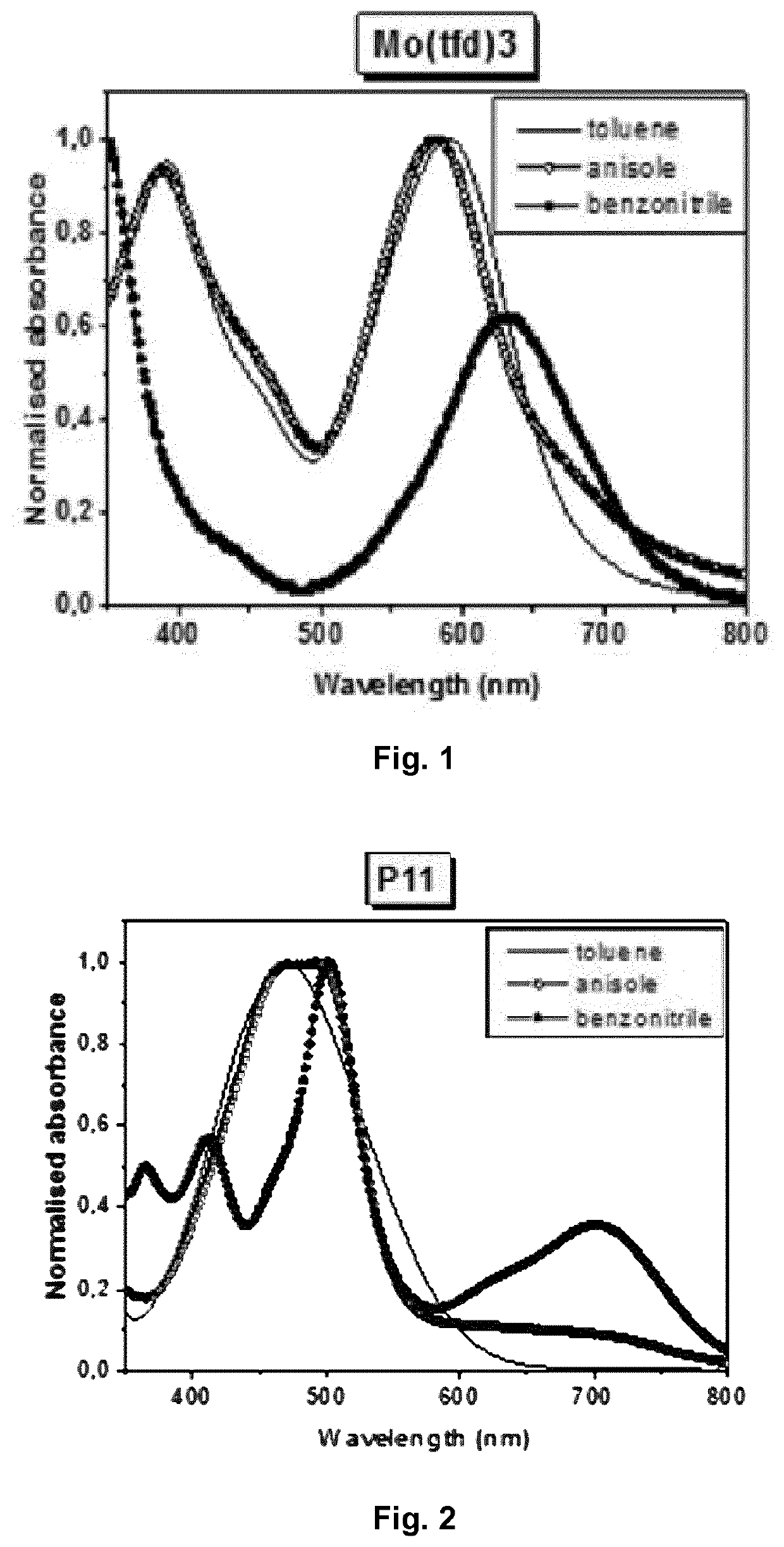
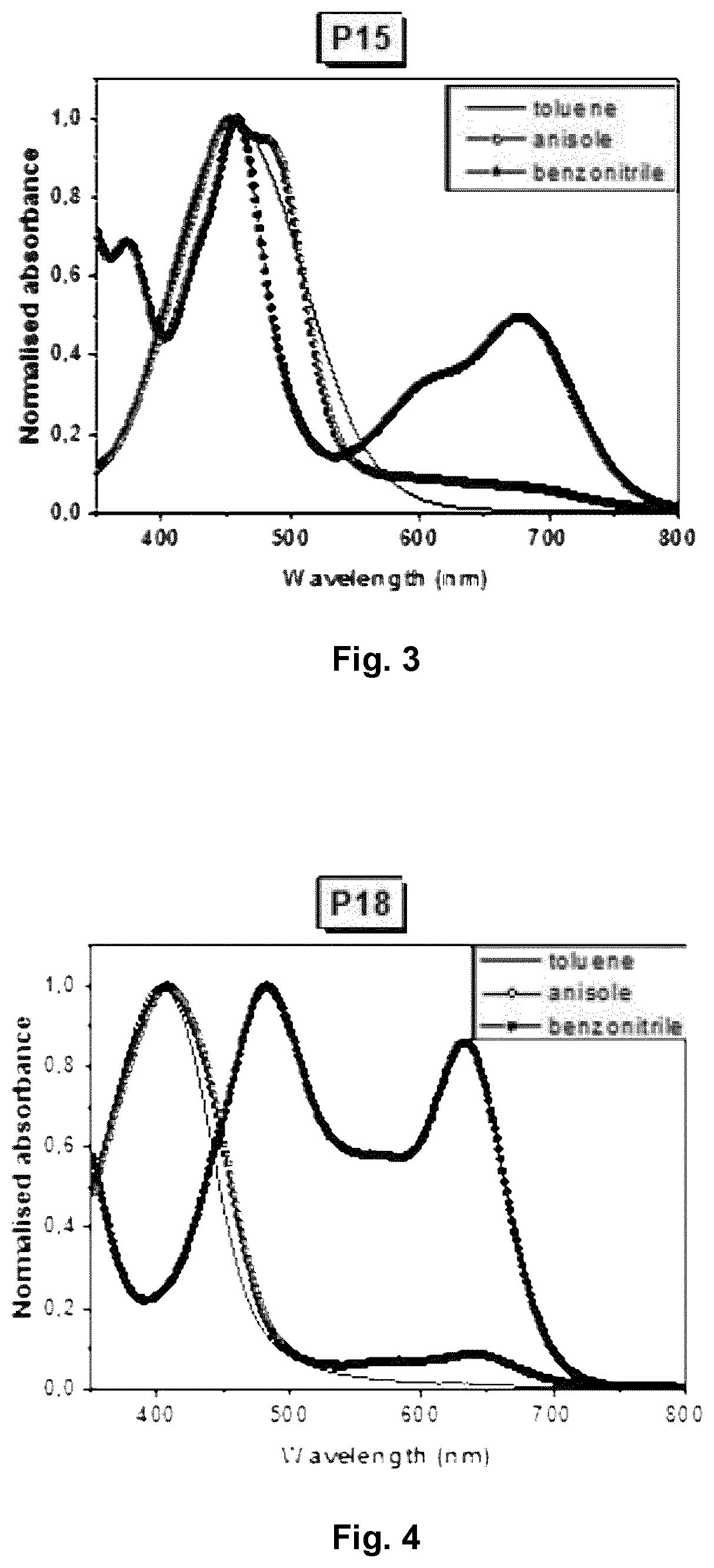
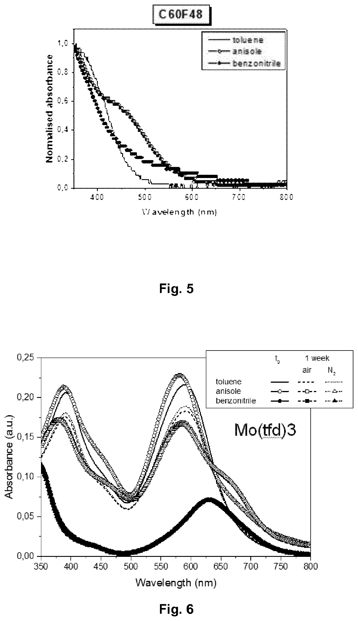

Image

  • Ink Composition for Forming an Organic Layer of a Semiconductor
  • Ink Composition for Forming an Organic Layer of a Semiconductor
  • Ink Composition for Forming an Organic Layer of a Semiconductor

Examples


Embodiment Construction

[0297]A standard OLED was used to test the inventive ink composition. The layers comprising the inventive OLED devices Inv-OLED-1 to Inv-OLED-4 were deposited sequentially as follows:[0298]ITO / Inventive HIL (40 nm) / HTM-1 (90 nm) / Host-1:Emitter-1 (5 wt %, 20 nm) / n-ETM-1 (30 nm) / LiQ (1 nm) / Al (100 nm)

[0299]First, the ITO on a glass substrate was cleaned using clean-room wipe and toluene solvent and subsequently plasma-cleaned. Subsequently, inv-ink1 was deposited by spin coating in a nitrogen glove box using the following recipe: spin step 1: acceleration=2 s, speed=750 rpm, t=5 seconds; spin step2: acceleration=2 s, speed=1200 rpm, t=30 seconds. The layer was dried on a hot plate at 60° C. for 1 min and subsequently a hard bake for cross-linking was applied for 30 mins at 150° C. All subsequent layers were deposited by vacuum thermal evaporation (VTE) at a pressure of about 1E-7 mbar and a deposition rate of about 1 Angstrom per second for the organic layers and about 3 Angstrom per ...


PUM

PropertyMeasurementUnit
Temperatureaaaaaaaaaa
Timeaaaaaaaaaa

Abstract

The present invention is directed to an ink composition for forming an organic semiconductor layer, wherein the ink composition comprises: —at least one p-type dopant comprising electron withdrawing groups; —at least one first auxiliary compound, wherein the first auxiliary compound is an aromatic nitrile compound, wherein the aromatic nitrile compound has about ≥1 to about ≤3 nitrile groups and a melting point of about <100° C., wherein the first auxiliary compound is different from the p-type dopant; and wherein the electron withdrawing groups are fluorine, chlorine, bromine and / or nitrile.

Description

TECHNICAL FIELD[0001]The present invention relates to an ink composition for forming an organic layer of a semiconductor, an electronic device, such as an OLED or solar cell, comprising the semiconductor layer, as well as a method of manufacturing the organic semiconductor layer.BACKGROUND ART[0002]Optoelectronic devices have been succeeded in commercialization and have been studied intensively for their scale up and cost-efficient fabrication. Typical examples of such optoelectronic device include organic electroluminescent devices or organic light emitting diodes (OLEDs), which are light emitting devices using a spontaneous light emitting phenomenon caused by coupling between electrons and holes upon the application of electric current to a device including a fluorescence- or phosphorescence-based light emitting layer between an anode and a cathode. Such OLEDs have a simple structure, are obtained by a simple process, and realize high image quality and a broad view angle. Further,...

Claims


Application Information

Patent Timeline
IPC IPC(8): C09D11/52H01L27/32H01L27/30C09D11/38C09D11/102H01L51/00
CPCC09D11/38C09D11/52C09D11/102H01L2251/556H01L51/506H01L51/0005H01L51/0052H01L2251/552H01L27/3246H01L51/5004H01L51/0043H01L51/5088H01L51/0084H01L27/3283H01L51/005H01L27/301H01L51/0039Y02E10/549H10K71/15H10K71/135H10K85/115H10K85/151H10K50/17H10K85/60H10K85/341H10K30/50H10K85/611H10K50/11H10K39/10H10K59/122H10K59/173H10K85/615H10K50/155H10K2101/30H10K2101/40H10K2102/361
Inventor LEDERER, KAYRUNGE, STEFFANGARNIER, JEROMETEICHLER, ANKE
Owner NOVALED GMBH
Learn More