
Damping device having a part mounted thereon

a technology of mounting part and mounting plate, which is applied in the direction of lightening support device, branching pipe, candle holder, etc., can solve the problems of achieving pretensioning, and achieve the effect of large pressing surface and minimal risk of tearing at the edges

Inactive Publication Date: 2015-04-14
ZF FRIEDRICHSHAFEN AG
View PDF11 Cites 0 Cited by
  • Summary
  • Abstract
  • Description
  • Claims
  • Application Information

AI Technical Summary

Benefits of technology

The invention is a tensioning band element that is used to hold together structural component parts. This tensioning band element is optimized for pretensioning force, meaning it does not require additional tightening means. The tensioning band element contacts tensioning surfaces on both the cylinder and mount-on part, ensuring only tensile loading at every point in circumferential direction. The tensioning band element is constructed as a seamless structural component part, which eliminates any weak points and allows for equal or excessive loading without risk of breakage. Additionally, the tensioning band element can be easily installed and monitored due to the presence of a contact surface on either the cylinder or mount-on part.

Problems solved by technology

The substantial disadvantage in this principle of construction consists in that the maximum pretensioning that can be achieved within the tensioning band element is determined by the opening force of the O-shaped deformation.

Method used


Image

  • Damping device having a part mounted thereon
  • Damping device having a part mounted thereon
  • Damping device having a part mounted thereon

Examples


Embodiment Construction

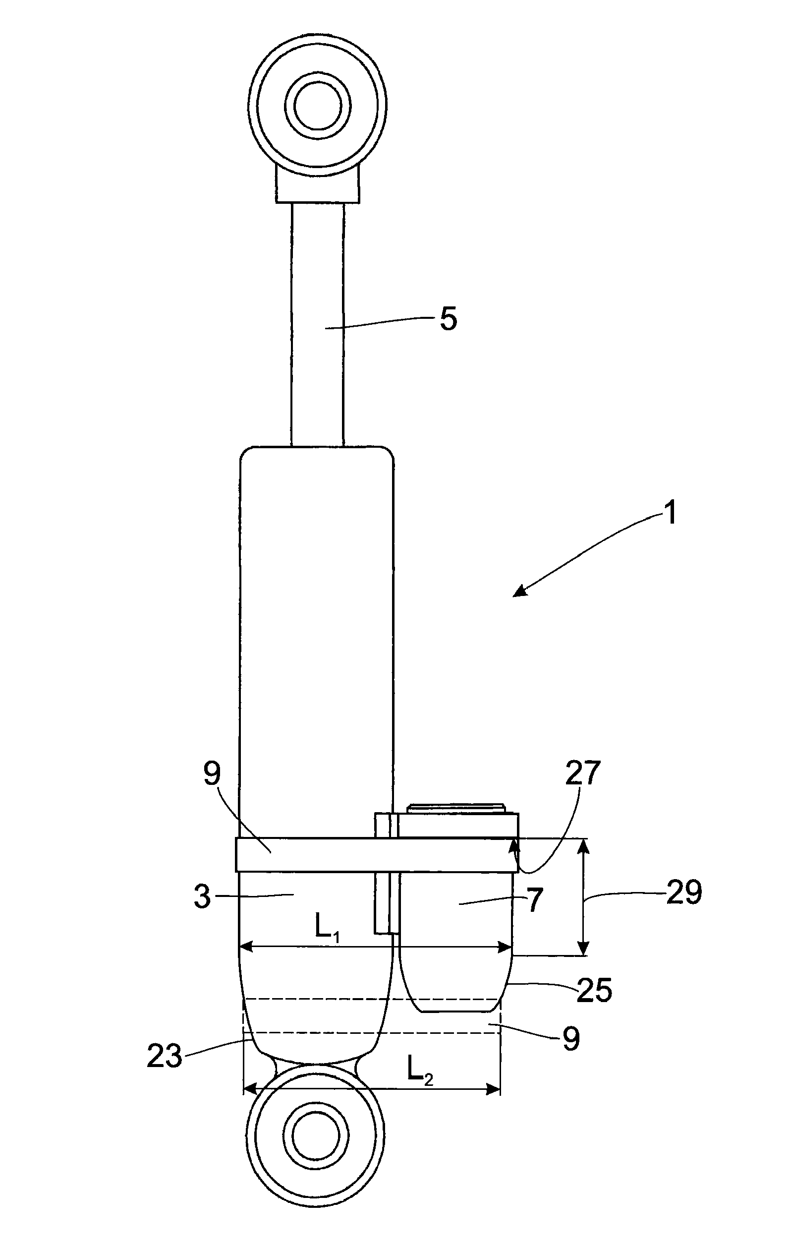
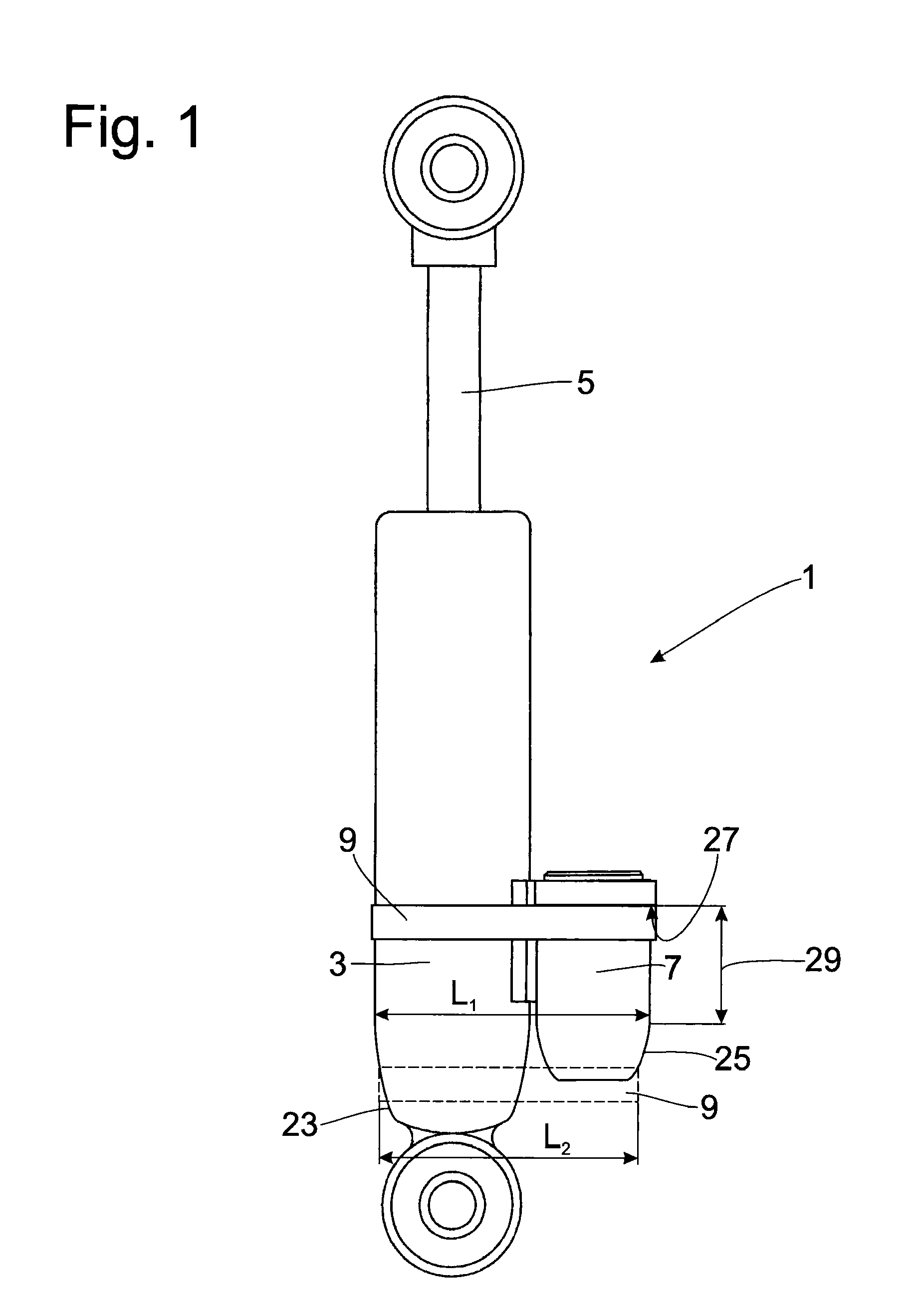
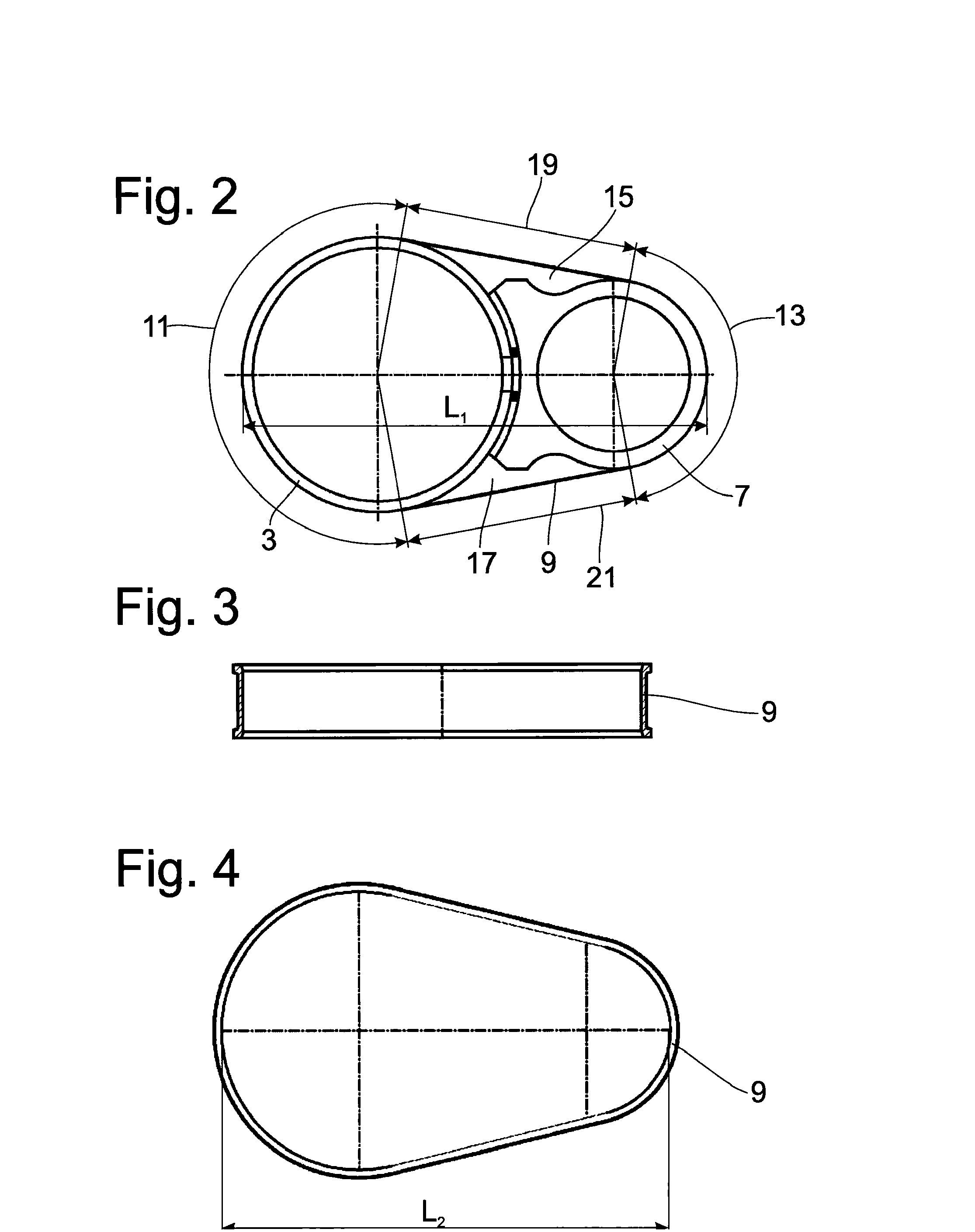
[0020]FIG. 1 shows a damping device 1 having a cylinder 3 which is under pressure and in which a piston rod 5 executes an axial stroke movement and accordingly changes the pressure in the cylinder filled with a damping medium in a pulsating manner. The cylinder 3 has a connection opening covered by the mount-on part 7. The mount-on part 7 is constructed as an axially parallel second cylinder having at least one annular tensioning band element 9 is fastened to a lateral surface of the cylinder 3. When viewed in conjunction with FIGS. 2 to 4, it can be seen that the tensioning band element 9 surrounds a circumferential region of the cylinder 3 and of the mount-on part 7. Both the cylinder 3 and the mount-on part 7 have at least one tensioning surface. The tensioning surfaces 11, 13 are confined to a circumferential region on these two structural component parts 3, 7. Based on the outer geometry of the cylinder 3 and mount-on part 7, FIG. 2 shows a cross section with radial indentation...


PUM


Abstract

A damping device includes a cylinder which is under pressure and which has a connection opening for a mount-on part which is fastened to an outer surface of the cylinder by means of an annular tensioning band element. The tensioning band element encircles the cylinder and the mount-on part on a circumferential region and, by its pretensioning, exerts a holding force on the mount-on part. The tensioning band element is underdimensioned in relation to the cross section of the cylinder and mount-on part and the distance between the two structural component parts and is expanded in a final mounting position in relation to a pre-mounting state in order to apply the pretensioning.

Description

BACKGROUND OF THE INVENTION[0001]1. Field of the Invention[0002]The present invention is directed to a damping device having a part mounted thereon.[0003]2. Background of the Invention[0004]A damping device having a cylinder which is under pressure and which has a connection opening for a mount-on part is known from DE 40 14 469 A1. The mount-on part is fastened to an outer surface of the cylinder by means of an annular tensioning band element. The tensioning band element encircles the cylinder and the mount-on part on a circumferential region and, by its pretensioning, exerts a holding force on the mount-on part. The tensioning band element according to DE 40 14 469 A1 has a larger circumference than is necessary for fastening the mount-on part to the cylinder. In order to generate the necessary pretensioning force, the tensioning band element is pretensioned in circumferential direction by means of an O-shaped loop. The substantial disadvantage in this principle of construction co...

Claims


Application Information

Patent Timeline
Patent Type & Authority Patents(United States)
IPC IPC(8): F16L3/223H02G7/12F16B2/08F16B7/04F16F9/32
CPCF16L41/12F15B15/08F16B2/08F16B7/0433F16F9/3271F16F2226/04F16F2230/0005
Inventor ACKERMANN, NORBERT
Owner ZF FRIEDRICHSHAFEN AG
Learn More