Illuminated telescoping cannula

a technology of telescoping cannulas and cannulas, which is applied in the field of surgical illumination, can solve the problems of optical fiber and other conventional waveguide plastics that may start to break down and degrade, and the cost of assembling fibers into endoscope tubes or other surgical devices may be high

Active Publication Date: 2015-04-14
INVUITY
View PDF87 Cites 36 Cited by
  • Summary
  • Abstract
  • Description
  • Claims
  • Application Information

AI Technical Summary

Benefits of technology

[0008]The waveguide sleeve may have many different geometries as, for example, a right circular cylinder, or the bottom edge may have any suitable angle relative to the axis of the sleeve bore to prevent tissue creep. The ability to move the waveguide cannula and the cannula sleeve relative to each other enables a surgeon to move the sleeve to accommodate tissue requirements without the need to move the illumination cable and the waveguide cannula. Similarly, if the surgeons light needs vary during the surgery, it is possible to move the illumination cable and the waveguide cannula without changing the position of the cannula sleeve.
[0011]A surgical illumination system may also include an illumination source, a generally cylindrical light waveguide having a distal end and a proximal end and a bore sized to accommodate one or more instruments or tools extending from the proximal end through the distal end, the waveguide conducting illumination energy from the proximal end to the distal end and projecting the illumination energy from the distal end, and an illumination conduit for conducting illumination energy from the illumination source to the proximal end of the light waveguide. A secondary cannula may be combined with the waveguide cannula to provide mechanical retraction and enable the waveguide cannula to be rotated relative to the secondary cannula as well as providing adjustable depth.
[0014]The surgical illumination systems may also be distributed pre-sterilized along with one or more generally used instruments and accessory parts that may be used by most surgeons. Thus a sterile waveguide may be supplied for a surgery and discarded after use minimizing parts to be reused, inventoried and resterilized.

Problems solved by technology

Although the cost of raw glass or plastic fiber is relatively inexpensive, the cost of assembling the fiber into an endoscope tube or other surgical device may be high.
Optical fiber is also extremely fragile and brittle.
During the assembly process or in the field after many sterilization cycles, optical fiber and other conventional waveguide plastics may start to break down and degrade.
Since the fiber is integrated into a medical tool, any damage to the fiber optics also results in damage to the tool, thus causing an expensive overhaul.
The relatively small size of the distal end of an illumination fiber also makes obscuration by blood or other material in a surgical site very likely and thus hinders to efficient surgery.
Another significant challenge in many conventionally illuminated procedures is cable management.
One of the challenges that face surgeons using illuminated tools is constant rotation of the illuminated tool to view different orientation angles.
When an illuminated tool is rotated, the fiber optic cable is forced to rotate around with the tool, thus causing interference.
Since the optical fiber cable is heavy, it will actually rotate the endoscope, often forcing the surgeon to keep one of their hands on the fiber optic cable to prevent unwanted spinning of the endoscope.
By allocating space to optical fiber illumination, the diameter of optics may be limited to maintain the smallest overall tool size.
Light that is not coupled from the fiber into the waveguide is lost light that cannot be used for illumination.
In addition, this lost light may have infrared components that contribute to heating of the coupling connectors, which are typically metal in fiber optic cables.
This heating may be significant enough to cause minor to major burns.
The user merely rotates the reflector / director rather than rotating the waveguide itself, which may be cumbersome with a fiber optic cable attached to the waveguide.

Method used


Image

  • Illuminated telescoping cannula
  • Illuminated telescoping cannula
  • Illuminated telescoping cannula

Examples


Embodiment Construction

[0071]The following disclosure generally refers to an optical waveguide and associated elements for conduction of light. This discussion is for example and the following disclosure may also be suitable for any electromagnetic radiation. The cross-sections illustrated are generally circular and may also adopt any suitable geometry.

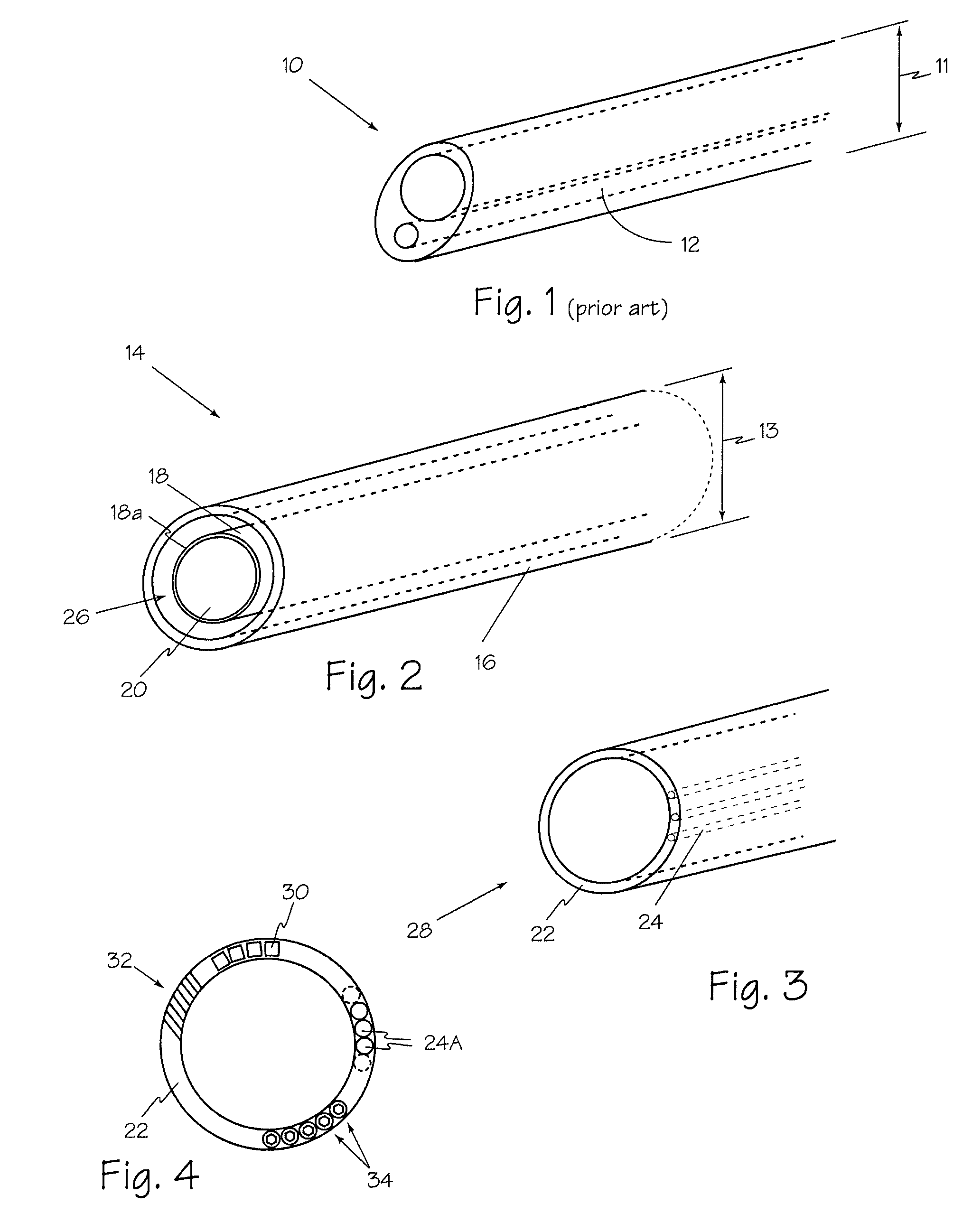
[0072]Referring now to FIG. 2, optical waveguide system 14 may accommodate any suitable surgical instrument such as for example, a drill, burr or endoscope 18 which is encased, enclosed or otherwise surrounded by optical waveguide sheath 16. An optical waveguide sheath according to the present disclosure is a generally annular or cylindrical shaped structure and may be manufactured separately and may be a single use device. In the event of a failure of an optical waveguide such as optical waveguide sheath 16, a replacement may be introduced immediately. One or more flow paths such as flow path 26 may be created between endoscope 18 and optical waveguide she...


PUM


Abstract

An illumination system includes an arthroscope, endoscope or other suitable surgical tool and an attachable cannula comprising a transparent or semi-transparent material capable of carrying light from the proximal end of the cannula to the distal end of the cannula, thereby illuminating the surgical field. The surgical field is thus illuminated through components that do not occupy space that may otherwise be used for the optics of the arthroscope. The arthroscopic illumination system further comprises one or more illumination sources disposed at the proximal end of the cannula. The illumination source may be optically coupled with the cannula at the hub or other appropriate location. The cannula comprises a sterilizable polymer which functions as a waveguide. A waveguide is a material medium that confines and guides light. When in use, the light source connected to the hub provides light which may be guided to the distal end of the cannula or any other suitable location. Thus, the sheath provides structure-guided illumination resulting in the illumination of the surgical site.

Description

RELATED APPLICATIONS[0001]The present application is a continuation-in-part of U.S. utility patent application Ser. No. 11 / 715,247, now U.S. Pat. No. 7,901,353 filed Mar. 6, 2007, which is a continuation-in-part of U.S. utility patent application Ser. No. 11 / 397,446 now U.S. Pat. No. 7,510,524 filed Apr. 3, 2006, which claims priority from U.S. provisional patent application Ser. No. 60 / 668,442 filed Apr. 4, 2005 and U.S. provisional patent application Ser. No. 60 / 724,717 filed Oct. 7, 2005.FIELD OF THE INVENTIONS[0002]The present invention relates generally to the field of surgical illumination and more specifically to surgical cannulas providing illumination.BACKGROUND OF THE INVENTIONS[0003]Currently optical fiber illumination elements such as element 12 shown in FIG. 1 are used exclusively in medical illumination where small packaging is critical. Although the cost of raw glass or plastic fiber is relatively inexpensive, the cost of assembling the fiber into an endoscope tube or...

Claims


Application Information

Patent Timeline
Patent Type & Authority Patents(United States)
IPC IPC(8): A61B1/06A61B18/18A61B1/00A61B1/07A61B1/313A61B1/317A61B19/00G02B23/24
CPCA61B1/3132A61B1/00096A61B1/00135A61B1/0607A61B1/07A61B1/317A61B19/5202G02B23/2469A61B2019/5206A61B1/32A61B17/3421A61B2017/3443A61B2017/3488A61B1/0669A61B17/0293A61B2090/306A61B90/30A61B17/3423A61B2017/3445A61B1/0676G02B6/4285
Inventor VAYSER, ALEX
Owner INVUITY
Why Eureka
Try Eureka