Wireless transmission with channel state perturbation

a technology of channel state and wireless transmission, applied in the direction of site diversity, polarisation/directional diversity, duplex signal operation, etc., can solve problems such as fading in wireless systems

Active Publication Date: 2015-04-14
KHANDANI AMIR KEYVAN
View PDF11 Cites 213 Cited by
  • Summary
  • Abstract
  • Description
  • Claims
  • Application Information

AI Technical Summary

Problems solved by technology

Wireless systems suffer from fading caused by multipath Radio Frequency (RF) wave propagation.

Method used


Image

  • Wireless transmission with channel state perturbation
  • Wireless transmission with channel state perturbation
  • Wireless transmission with channel state perturbation

Examples


example 1

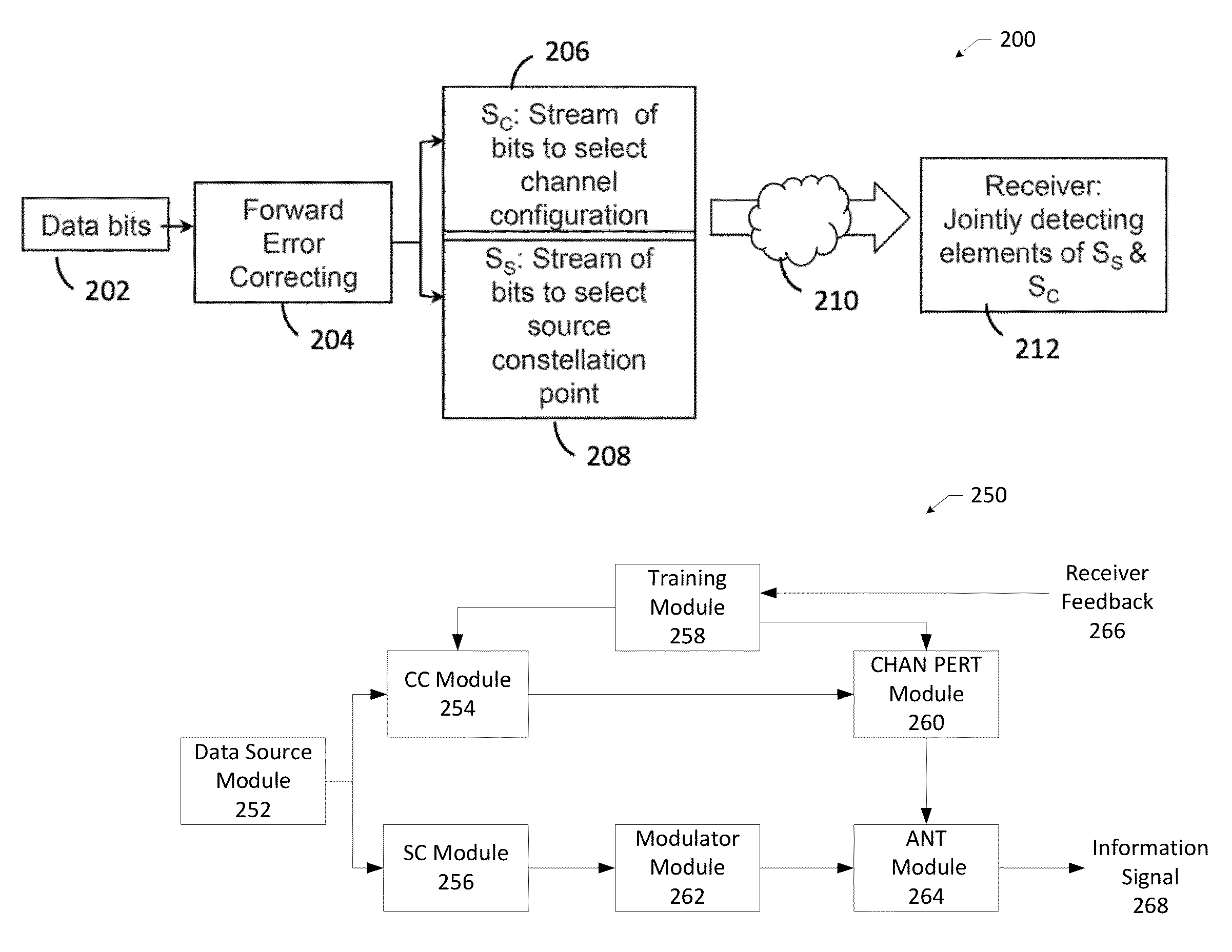
[0036]Assume transmitter has access to 1024 possibilities (channel states) to perturb the channel and starts transmitting them one by one indexed from 0 to 1023 (transmits a fixed pilot and changes the channel from #0 to #1023 one after other), and then selects a subset of size say 256, by the receiver notifying the transmitter the selected elements indexed by values from 0 to 1023 are acceptable (total of 256). Acceptable may signify that the received signal may have a signal quality over a predetermined threshold (e.g. SNR). Then, transmitter and receiver use the selected 256 elements indexed from 0 to 255 in agreement with the original implicit ordering they were tried by the transmitter during the learning phase.

[0037]Further examples of the training phase of media-based communications include the following.

example 2

[0038]There are 28 possibilities for channel configurations indexed by 0, . . . 255. Such an embodiment transmits 6 bits per channel use. Phase I: Transmitters fixes the source at 1 and activates the possible channel configurations one after the other in the same order as these are indexed. Meanwhile, receiver measures the corresponding received signals. The receiver has measured 28 channel configurations. The receiver selects the best subsets of size 1, 2, 22, 23, 24, 25, 26, to be potentially used together with a source constellation of sizes 26, 25, 24, 23, 22, 2, 1 (all 7 options provide the required bit rate of 6 bits per channel use). Receiver decides which of these 7 options would perform better (e.g. lower transmit energy for a given error probability) and inform the transmitter. Information sent to transmitter can be as simple as sending the indices of the selected configurations, or include some additional information such as a scale factor to increase transmit energy depe...

example 3

[0039]There are 28 possibilities for channel configurations indexed by 0, . . . 255. Such an embodiment transmits 6 bits per channel use. Further, such an embodiment may have a fixed policy and always embeds 2 bits in the source variations and 4 bits in the channel variations. Transmitter fixes the source at 1 and activates the possible channel configurations one after the other in the same order as these are indexed. Meanwhile, receiver measures the corresponding received signals. Receiver accepts or rejects each configuration and in parallel with the forward link sends a yes / no answer back to the transmitter to communicate its decision. If the number of selected configurations for inclusion in the selected subset is less than the desired value of 26=64, then training phase repeats using those configurations that were not accepted in the first phase, and so on, until a selected subset of size 64 is agreed upon. A variety of such selection policies and feedback mechanisms are possib...


PUM


Abstract

Generating a channel codebook by identifying a subset of antenna configurations from a plurality of antenna configurations of an antenna associated with a transmitter by: transmitting a sequence of symbols from the transmitter to a receiver using the plurality of antenna configurations, wherein each antenna configuration provides a unique transmission characteristic to the receiver; receiving feedback from the receiver that identifies the subset of antenna configurations; and, generating channel codebook entries corresponding to the subset of antenna configurations; and, transmitting data from the transmitter to the receiver using the channel codebook.

Description

CROSS-REFERENCE TO RELATED APPLICATIONS[0001]The present application is a non-provisional filing of, and claims benefit under 35 U.S.C. §119(e) from, U.S. Provisional Patent Application Ser. No. 61 / 646,312, filed May 13, 2012, and U.S. Provisional Patent Application Ser. No. 61 / 771,815, filed Mar. 2, 2013, both of which are hereby incorporated herein by reference. In addition, this application is related to the following applications, all of which are also incorporated herein by reference: U.S. application Ser. No. 13 / 893,288, entitled Full Duplex Wireless Transmission with Self-Interference Cancellation, filed May 13, 2013, U.S. application Ser. No. 13 / 893,297, entitled Full Duplex Wireless Transmission with Channel Phase-Based Encryption, filed May 13, 2013, and U.S. application Ser. No. 13 / 893,299, entitled Distributed Collaborative Signaling in Full Duplex Wireless Transceivers, filed May 13, 2013.BACKGROUND OF THE INVENTION[0002]Current wireless systems are based on embedding i...

Claims


Application Information

Patent Timeline
Patent Type & Authority Patents(United States)
IPC IPC(8): H04B7/02H04B7/04H04B7/06H04B7/10H04L5/14H04W12/04H04W16/14
CPCH04W16/14H04B7/0413H04L5/14H04W12/04H04B7/0478H04B7/026H04B7/0417H04B7/0626H04B7/10H04B7/0669H04B1/123H04B1/525H04L1/1825H04L1/1896H04L2001/0097H04L1/18
Inventor KHANDANI, AMIR KEYVAN
Owner KHANDANI AMIR KEYVAN
Why Eureka
Try Eureka