Electrically chargeable energy store device and method of charging

a technology of energy storage and energy storage device, which is applied in the direction of electrochemical generators, secondary cell servicing/maintenance, transportation and packaging, etc., can solve the problems of lithium ion batteries that may burst, batteries that may react sensitively to charging errors, etc., and achieve the effect of easy production

Active Publication Date: 2015-04-21
ROBERT BOSCH GMBH
View PDF8 Cites 2 Cited by
  • Summary
  • Abstract
  • Description
  • Claims
  • Application Information

AI Technical Summary

Benefits of technology

[0008]Based on the differences between the scanned cell voltages, a debalancing of the energy cells is able to be determined. Based on the debalancing, the setpoint charging current may be determined in such a way that an energy cell having a high cell voltage is not overcharged, while another energy cell having a lower cell voltage continues to be charged. Because of that, the debalancing of the energy cells may be minimized, so that the energy store in total is able to be charged more highly. The energy able to be obtained from the energy store is able to be maximized thereby.
[0010]The processing device may be equipped additionally to determine the charging current based on the maximum cell voltages assigned to the energy cells. A maximum cell voltage for all the energy cells may be used, or an individual maximum cell voltage may be assigned to each energy cell. By the observation of the difference between the maximum cell voltage and the actual cell voltage, the setpoint charging current may be determined in an improved manner, particularly in a last section of the charging process of the energy store, in such a way that the degree of charging of the energy store is maximized.
[0012]As the charging state increases, that is, as the charging of the energy store progresses, the temperature of the energy store may be used as a further indication for a remaining absorption capability of the energy store. By taking into account the temperature of the energy store, one is able to avoid a charging error that may occur in response to the exceeding of the temperature of the energy store above a predetermined place value. For this reason, the energy store may be charged in a more sparing manner and safety during the charging process may be increased.
[0017]The charging device may include a first device for providing a first signal as a function of the charging current, a second device for providing a second signal as a function of the setpoint charging current and a comparing device for controlling the charging current as a function of the two signals. In that way, the charging current may be limitable to the setpoint charging current in a simple and reliable manner.
[0018]In one preferred specific embodiment, the signals are represented by voltages, and the second device includes a square-wave generator and a post-connected low-pass filter. Thereby, the second signal is easily produced, particularly by a digital processing device. The determination and processing of the setpoint charging current may consequently be carried out in a cost-saving manner and highly integrated essentially in a digital manner, while an analog activation of the limiting device may be implemented using simple means.

Problems solved by technology

Some batteries may react sensitively to a charging error, such as overcharging.
Lithium ion batteries may burst, for example, which may be accompanied by an explosion or a fire.
In this context, however, the state of charge of other cells, whose cell voltages are below the respectively specified maximum cell voltages, may not yet have reached a maximum state of charge, so that on an overall basis, the battery is only partially charged.

Method used


Image

  • Electrically chargeable energy store device and method of charging
  • Electrically chargeable energy store device and method of charging
  • Electrically chargeable energy store device and method of charging

Examples


Embodiment Construction

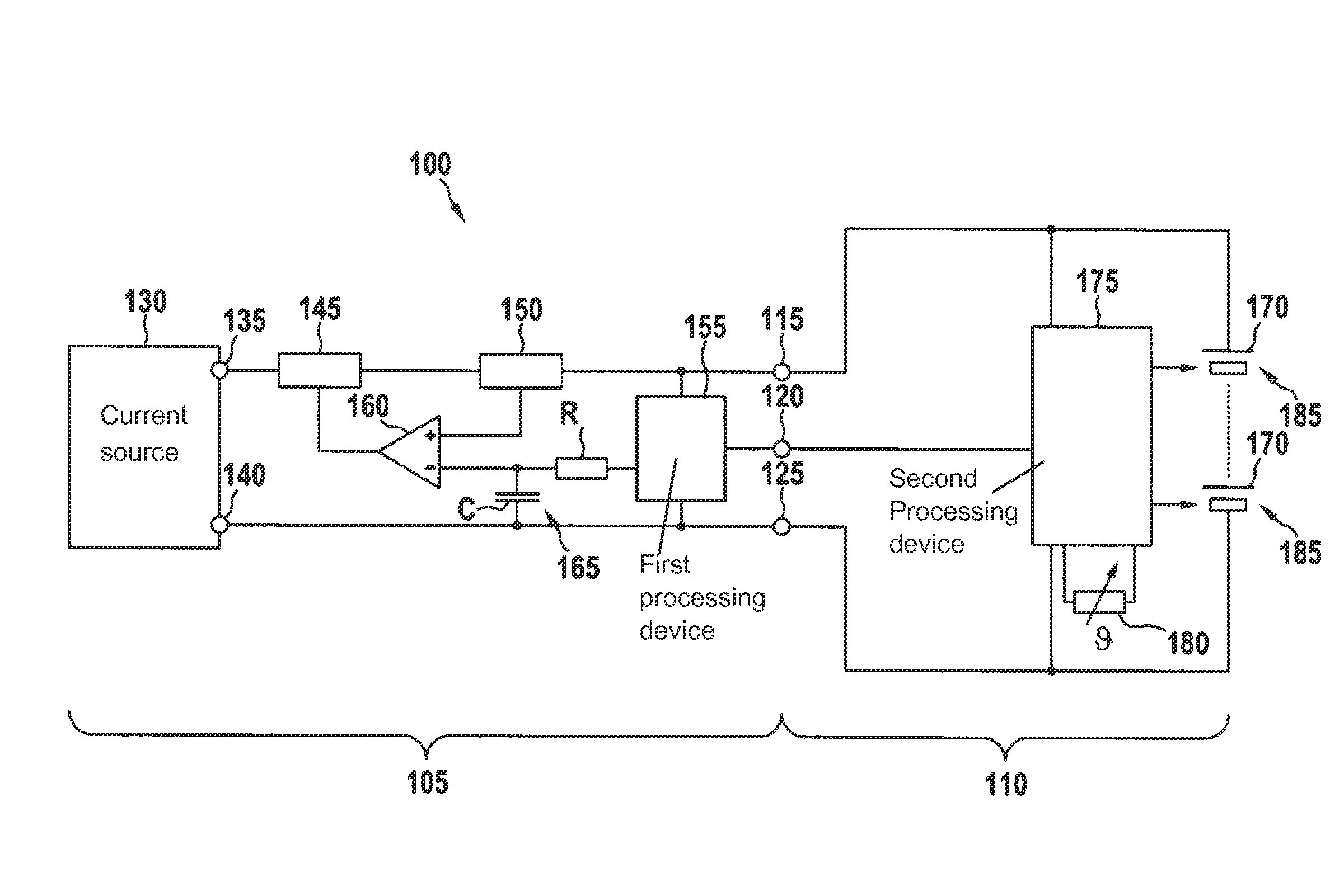
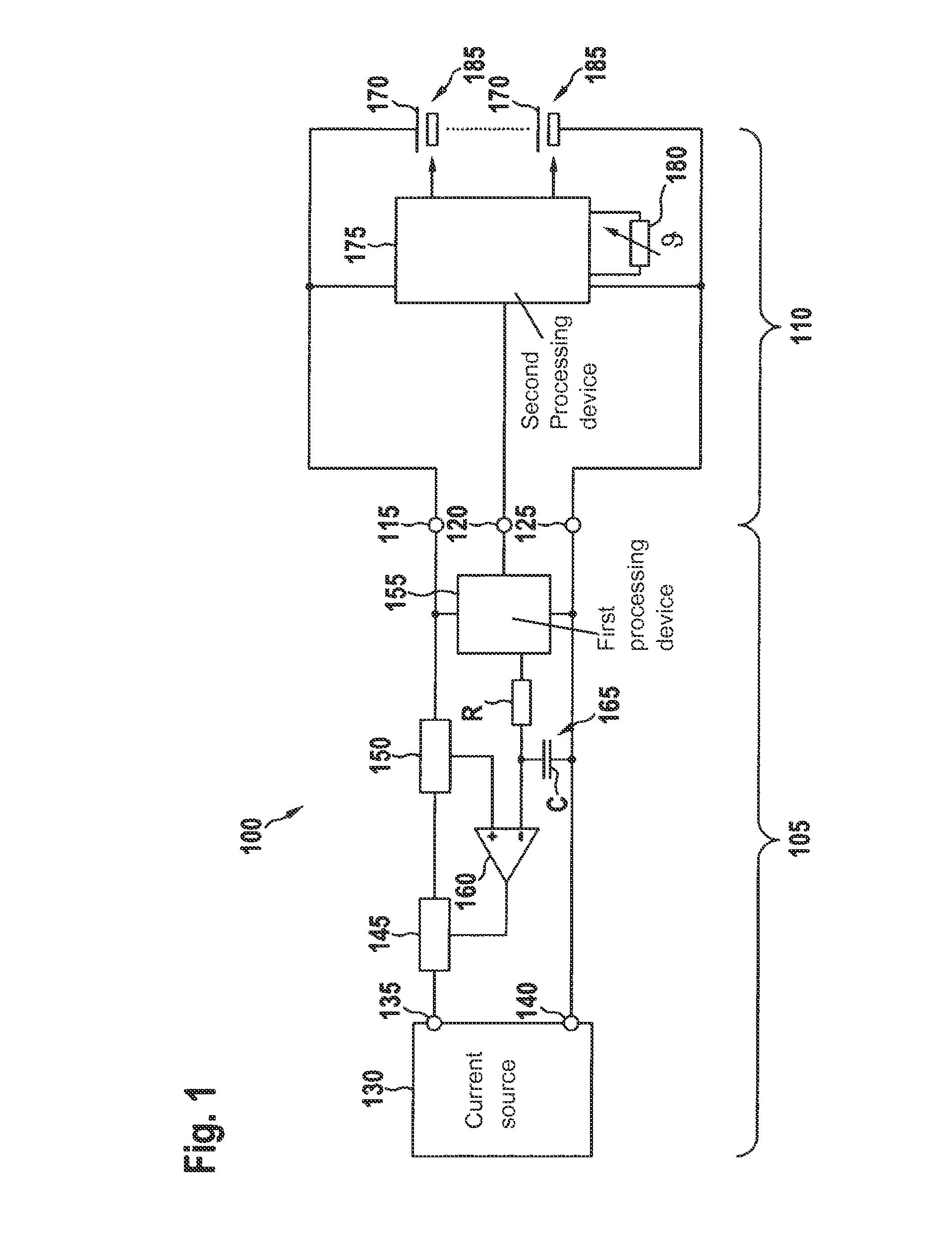
[0026]FIG. 1 shows a system made up of a charging device 105 and an energy store 110. Charging device 105 is electrically connected to energy store 110 using a first connection 115, a second connection 120 and a third connection 125.

[0027]Charging device 105 includes a current source 130 having a first terminal 135 and a second terminal 140. Furthermore, charging device 105 includes a limiting device 145, a current sensor150, a first processing device 155, a resistor R, a capacitor C and a comparator 160.

[0028]A charging current provided by current source 130 flows from first terminal 135 to limiting device 145, from there to current sensor 150 and on to first connection 115. After the charging current has flowed within energy store 110 from first connection 115 to third connection 125, it flows on to the second terminal of current source 130, so that the circuit is closed. Limiting device 145 is controlled by an output signal of comparator 160. Comparator 160 has a positive (noninv...


PUM

PropertyMeasurementUnit
cell voltagesaaaaaaaaaa
voltagesaaaaaaaaaa
charging currentaaaaaaaaaa

Abstract

An electrically chargeable energy store includes a plurality of energy cells connected in series, a scanning device for the cell voltages of the energy cells, and a processing device for determining a setpoint charging current through the energy cells based on the scanned cell voltages. The processing device is equipped to determine the setpoint charging current as a function of differences between the scanned cell voltages. A method for charging an electrically chargeable energy store includes steps of scanning of the cell voltages of the energy cells, determining a setpoint charging current through the energy cells based on the differences of the scanned cell voltages, and limiting of a charging current flowing through the energy cells to the determined setpoint charging current.

Description

BACKGROUND OF THE INVENTION[0001]1. Field of the Invention[0002]The present invention relates to an energy store and a charging method.[0003]2. Description of Related Art[0004]An electric battery includes a number of electric energy cells which are connected to one another in series. To charge the battery, a predetermined charging current is led through the energy cells. During the course of the charging process, the cell voltages of the energy cells in each case approach a predetermined maximum cell voltage. Some batteries may react sensitively to a charging error, such as overcharging. Lithium ion batteries may burst, for example, which may be accompanied by an explosion or a fire.[0005]In order to avoid a charging error and to end the charging process in time, it is customary to switch off the charging current when one of the energy cells has reached the maximum cell voltage assigned to it. In this context, however, the state of charge of other cells, whose cell voltages are belo...

Claims


Application Information

Patent Timeline
Patent Type & Authority Patents(United States)
IPC IPC(8): H01M10/44H01M10/46H01M10/42H01M10/48H02J7/00
CPCH01M10/425H01M10/441H01M10/443H01M10/482H02J7/0022H02J7/0081H02J7/0091H01M2010/4271H02J7/007184Y02E60/10H02J7/0014H02J7/007194
Inventor MACK, JUERGENCLAUS, HOLGER
Owner ROBERT BOSCH GMBH
Why Eureka
Try Eureka