Thermodynamic cycle system for moving vehicle

a technology of moving vehicle and cycle system, which is applied in the direction of battery/fuel cell control arrangement, domestic cooling apparatus, lighting and heating apparatus, etc., can solve the problems of inability to lower the temperature of the cooling medium, the air conditioning system set up on the moving vehicle is not equipped, etc., to enhance the energy-saving effect of indoor air conditioning, enhance the adjustment function, and minimize the effect of energy consumption

Inactive Publication Date: 2011-03-31
HITACHI LTD
View PDF6 Cites 38 Cited by
  • Summary
  • Abstract
  • Description
  • Claims
  • Application Information

AI Technical Summary

Benefits of technology

[0004]In order to increase the activation of the heat-liberation component without lowering the capability of the air-conditioning system, the following scheme is conceivable: Namely, like the technology disclosed in, e.g., JP-A-8-258548, the energy-saving implementation of the air-conditioning system is accomplished by configuring a system where the heat released from the heat-liberation component can be taken advantage of as the heat source at the time of the heating operation of the refrigeration cycle. This scheme makes it possible to suppress the energy taken out by the air-conditioning system from the energy source for the heat-liberation component. Nevertheless, in the system configuration where, like the technology disclosed in JP-A-8-258548, the exhaust heat is utilized in a secondary manner, the following drawbacks are conceivable: Namely, the utilization efficiency lowers in accompaniment with the conversion of the thermal energy, and the energy-saving effect lowers accordingly. Here, the exhaust-heat utilization in the secondary manner is such that the exhaust heat from the heat-liberation component is collected into the refrigeration cycle, and after that, the exhaust heat is utilized for the air conditioning. These circumstances require the construction of a system configuration which allows an enhancement in the energy-saving effect.
[0006]According to one of the aspects of the present inventions, it is provided with a moving vehicle thermodynamic cycle system which allows the accomplishment of the energy-saving implementation of the indoor air conditioning, and which allows the enhancement in the adjustment functionality for the temperature of the heat-liberation component.
[0007]According to another aspect of the present invention, it is provided with a thermodynamic cycle system, including a thermodynamic cycle circuit which is separated into a primary-side thermodynamic cycle circuit for performing heat exchange with an outdoor side, and a secondary-side thermodynamic cycle circuit for performing heat exchange with an indoor side and a heat-liberation component side, wherein the primary-side thermodynamic cycle circuit is constituted with a refrigeration cycle system, the secondary-side thermodynamic cycle circuit being constituted with two heat-transferring systems through which heat-transferring media flow independently of each other, an intermediate heat exchanger being provided between the refrigeration cycle system and each of the two heat-transferring systems, so that a refrigerant of the refrigeration cycle system and the heat-transferring medium of each of the two heat-transferring systems can perform the heat exchange with each other, an indoor heat exchanger being further provided in each of the two heat-transferring systems for performing the heat exchange with the heat-liberation component side, so that the heat-transferring medium of each of the two heat-transferring systems for performing the heat exchange with the heat-liberation component side, and air which is taken into the indoor side can perform the heat exchange with each other.
[0008]According to one of the representative present inventions, the thermal energy that is obtained by the temperature adjustment of the heat-liberation component is utilized for the indoor air conditioning. This feature makes it possible to accomplish the minimization of the energy needed for the indoor air conditioning, thereby allowing the accomplishment of the energy-saving implementation of the indoor air conditioning. What is more, according to the one of the representative present inventions, the thermal energy obtained by the temperature adjustment of the heat-liberation component is directly utilized for the indoor air conditioning. This feature allows the enhancement in the energy-saving effect on the indoor air conditioning. Consequently, according to the one of the representative present inventions, it becomes possible to suppress the energy taken out by the air-conditioning system from the energy source for the heat-liberation component.
[0009]Also, according to further aspect of the present invention, the thermal energy that is used for the indoor air conditioning is utilized for the temperature adjustment of the heat-liberation component. This feature makes it possible to make a wide-range adjustment of the temperature of the heat-transferring media for adjusting the temperature of the heat-liberation component. This wide-range adjustment allows the temperature of the heat-liberation component to be made variable without being influenced by the peripheral environment's state. Consequently, according to the one of the representative present inventions, it becomes possible to adjust the temperature of the heat-liberation component into an appropriate temperature at which the heat-liberation component can operate with a high efficiency. This feature permits the heat-liberation component to operate with the high efficiency.

Problems solved by technology

The air-conditioning system set up on the moving vehicle is not equipped with an energy source which is specifically dedicated to the air-conditioning system itself.
In the heat exchange between the air and the cooling medium, however, the temperature of the cooling medium cannot be lowered down to a temperature which is lower than the temperature of the air.
As a result, if, e.g., at the high-temperature time in summer, the heat-liberation amount (i.e., temperature) of the heat-liberation component has increased, it becomes increasingly difficult to permit the temperature of the heat-liberation component to come closer to the appropriate temperature, at which the heat-liberation component can operate with a high efficiency.

Method used


Image

  • Thermodynamic cycle system for moving vehicle
  • Thermodynamic cycle system for moving vehicle
  • Thermodynamic cycle system for moving vehicle

Examples


1st embodiment

[0094]Referring to FIG. 1 through FIG. 8, the explanation will be given below regarding a first embodiment of the thermodynamic cycle system set up on the EV 1000.

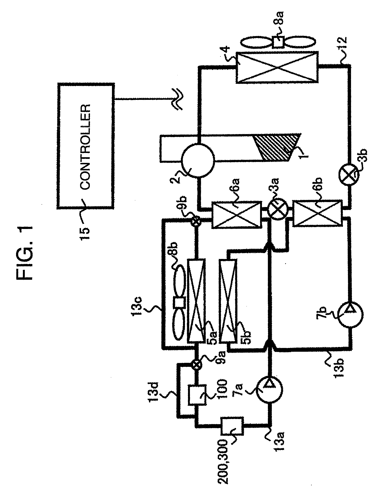
[0095]FIG. 1 through FIG. 8 illustrate the configuration of the thermodynamic cycle system set up on the EV 1000.

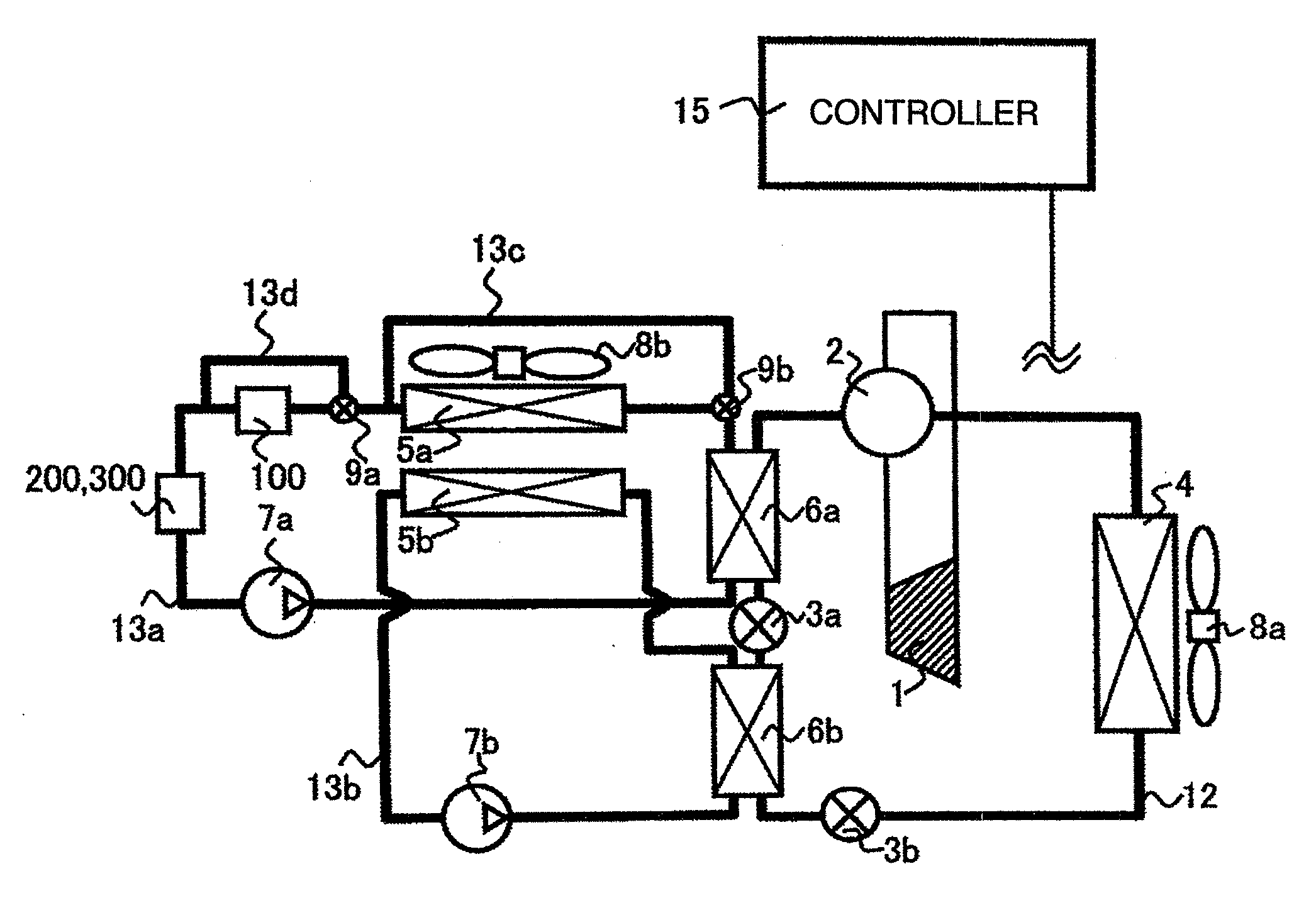
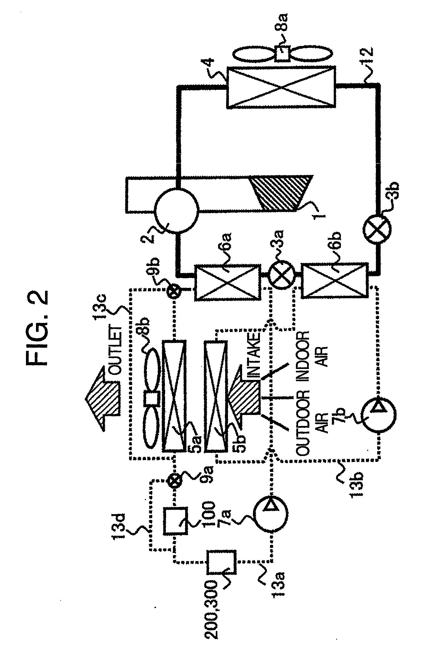
[0096]Incidentally, FIG. 2 illustrates, with the solid line, a refrigerant pipe 12 (i.e., primary-side thermodynamic cycle circuit) through which a refrigerant such as HFC-134a flows. Also, FIG. 2 illustrates, with the dotted lines, heat-transferring medium pipes 13a and 13b (i.e., secondary-side thermodynamic cycle circuit) through which liquid-state cooling agents (i.e., heat-transferring media) such as water or antifreeze solution flow.

[0097]The thermodynamic cycle system set up on the EV 1000 includes a thermodynamic cycle circuit. As illustrated in FIG. 1 and FIG. 2, this thermodynamic cycle circuit is separated into the primary-side thermodynamic cycle circuit for performing heat exchange with an outdoor s...

2nd embodiment

[0143]Referring to FIG. 9 and FIG. 10, the explanation will be given below concerning a second embodiment of the thermodynamic cycle system set up on the EV 1000.

[0144]The present embodiment is a modified embodiment of the first embodiment. Concretely, the correspondence relationship between the intermediate heat exchangers 6a and 6b and the first and second heat-transferring systems is a relationship which is inversed to the one in the first embodiment. Namely, the cooling liquid in the first heat-transferring system and the refrigerant in the refrigeration cycle system are heat-exchanged with each other by the intermediate heat exchanger 6b which is deployed between the pressure reducers 3a and 3b. Also, the cooling liquid in the second heat-transferring system and the refrigerant in the refrigeration cycle system are heat-exchanged with each other by the intermediate heat exchanger 6a which is deployed between the pressure reducer 3a and the four-way valve 2.

[0145]The other confi...

3rd embodiment

[0148]Referring to FIG. 11, the explanation will be given below regarding a third embodiment of the thermodynamic cycle system set up on the EV 1000.

[0149]The present embodiment is an improved embodiment of the second embodiment. In the present embodiment, an outdoor heat exchanger 14 is provided on the bypass pipe 13c. The outdoor heat exchanger 14 is deployed in a side-by-side manner with the outdoor heat exchanger 4 such that the exchanger 14 is deployed on the upstream side of the outdoor heat exchanger 4 with reference to the flow of the air sent by the fan 8a. Based on this deployment, the outdoor heat exchanger 14 performs the heat exchange between the air sent by the fan 8a and the cooling liquid flowing through the bypass pipe 13c. Also, in the present embodiment, the three-way valve 9b is deployed between the pump 7a and the intermediate heat exchanger 6b. Thanks to this deployment of the valve 9b, it is made possible to cause the cooling liquid before being heat-exchanged...


PUM


Abstract

A thermodynamic cycle system for a moving vehicle, including a refrigeration cycle system through which a refrigerant flows, a first heat-transferring system through which a heat-transferring medium flows, the heat-transferring medium being used for adjusting temperatures of heat-liberation components, a second heat-transferring system through which a heat-transferring medium flows, the heat-transferring medium being used for adjusting an indoor air state, an intermediate heat exchanger provided between the refrigeration cycle system and the first heat-transferring system, an intermediate heat exchanger provided between the refrigeration cycle system and the second heat-transferring system, an indoor heat exchanger provided in the first heat-transferring system, and an indoor heat exchanger provided in the second heat-transferring system.

Description

BACKGROUND OF THE INVENTION[0001]The present invention relates to a thermodynamic cycle system set up on a moving vehicle.[0002]As conventional technologies concerning a thermodynamic cycle system set up on a moving vehicle, there have been known technologies disclosed in, e.g., JP-A-2008-230594 and JP-A-8-258548. In JP-A-2008-230594, there is disclosed the technology for enhancing the heating capability as follows: An electric heater is provided on the refrigeration cycle system. Then, the heat occurring in a heating cycle of the refrigeration cycle and the heat generated by the electric heater are co-used simultaneously, thereby enhancing the heating capability. Also, in JP-A-8-258548, there is disclosed the technology for enhancing the heating capability as follows: The heat exchange is performed between a cooling liquid, which receives the heat released from a heat-liberation component, and a refrigerant of the refrigeration cycle. In this way, the heat released from the heat-li...

Claims


Application Information

Patent Timeline
Patent Type & Authority Applications(United States)
IPC IPC(8): F25D31/00F25B1/00F25B41/00
CPCB60H1/00278B60H2001/00928B60H2001/00307B60H1/00392B60L1/003B60L2200/18B60L2200/36B60L2240/34B60L2240/36B60L2240/425B60L2240/525B60L2240/545B60L58/26B60L58/27B60H1/32281Y02T10/64Y02T10/70
Inventor ARAI, MASATSUGUNASU, SHINGOMATSUSHIMA, HIROAKIKOTANI, MASANAOKOMATSU, TOMOHIROSEKIYA, SACHIO
Owner HITACHI LTD
Why Eureka
Try Eureka