
Energy store method and charging method

a technology of energy storage and charging method, which is applied in the direction of electrochemical generators, secondary cell servicing/maintenance, transportation and packaging, etc., can solve the problems of lithium ion batteries that may burst, batteries that may react sensitively to charging errors, etc., and achieve the effect of easy production

Active Publication Date: 2012-09-13
ROBERT BOSCH GMBH
View PDF3 Cites 12 Cited by
  • Summary
  • Abstract
  • Description
  • Claims
  • Application Information

AI Technical Summary

Benefits of technology

The present invention relates to a method for charging an electrically chargeable energy store, which includes a plurality of energy cells connected in series. The method includes steps of scanning the cell voltages of the energy cells, determining a setpoint charging current through the energy cells based on the differences of the scanned cell voltages, and limiting the charging current flowing through the energy cells to the determined setpoint charging current. The setpoint charging current may be determined based on at least one of the highest scanned cell voltage, the highest maximum cell voltage of one of the energy cells, and a ratio of cell voltages. The method may be executed on the processing device of the energy store or a further processing device in the area of the charging device or the adapter described. The technical effect of the invention is to maximize the charging of the energy store by fully charging the cells as independently as possible of their individual load-carrying capacity, while avoiding charging errors that may occur due to exceeding the temperature of the energy store.

Problems solved by technology

Some batteries may react sensitively to a charging error, such as overcharging.
Lithium ion batteries may burst, for example, which may be accompanied by an explosion or a fire.
In this context, however, the state of charge of other cells, whose cell voltages are below the respectively specified maximum cell voltages, may not yet have reached a maximum state of charge, so that on an overall basis, the battery is only partially charged.

Method used


Image

  • Energy store method and charging method
  • Energy store method and charging method
  • Energy store method and charging method

Examples


Embodiment Construction

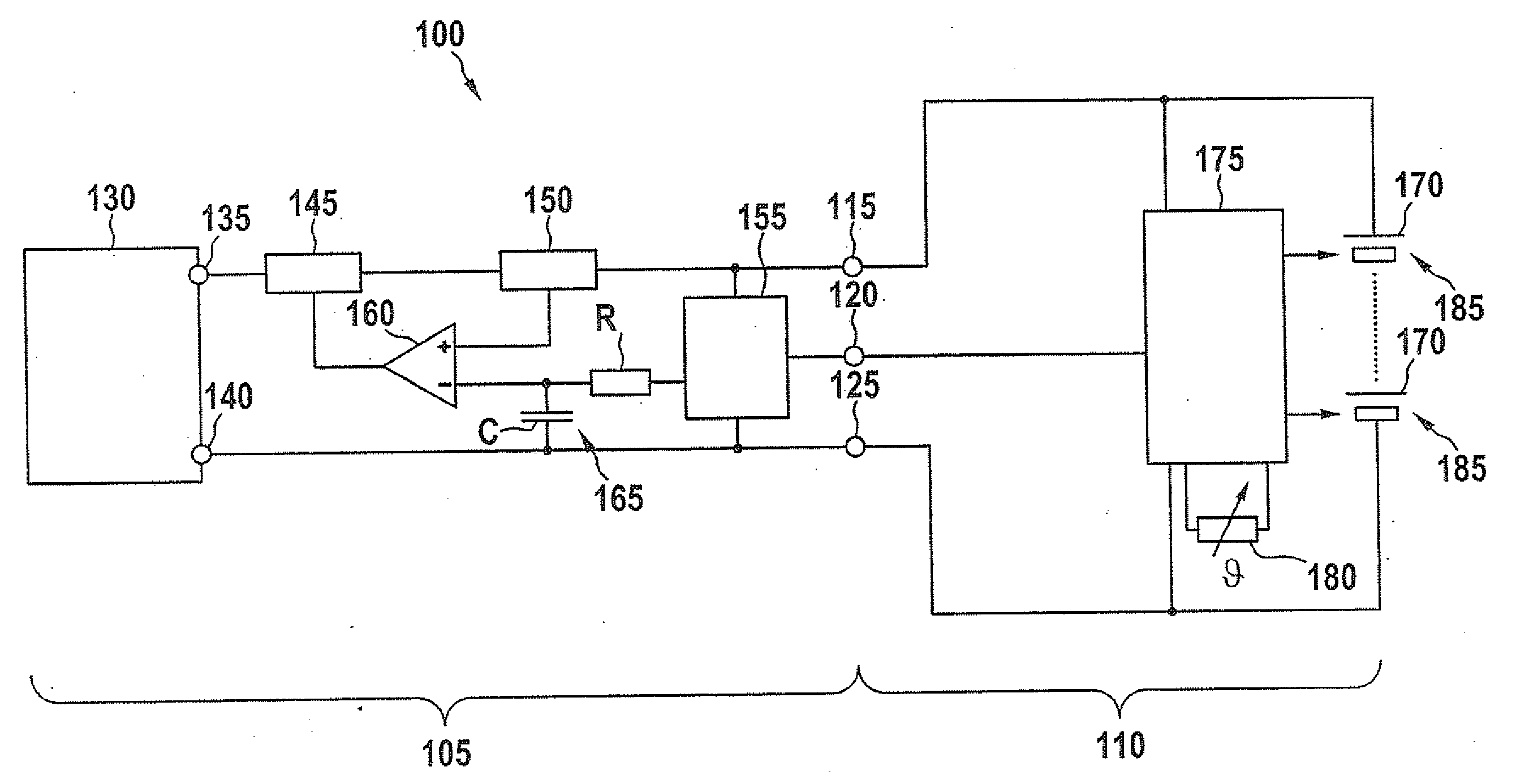
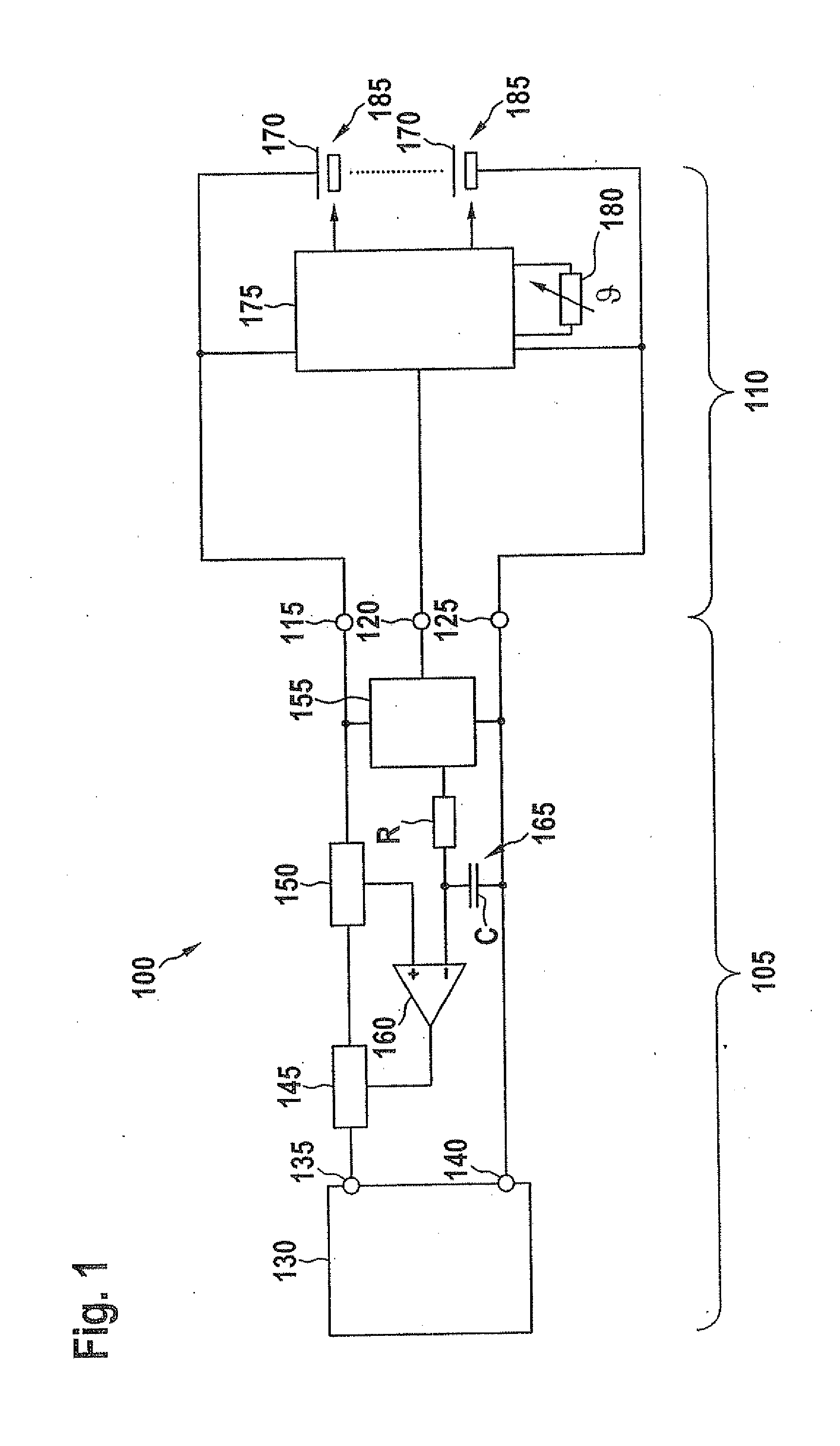
[0026]FIG. 1 shows a system made up of a charging device 105 and an energy store 110. Charging device 105 is electrically connected to energy store 110 using a first connection 115, a second connection 120 and a third connection 125.

[0027]Charging device 105 includes a current source 130 having a first terminal 135 and a second terminal 140. Furthermore, charging device 105 includes a limiting device 145, a current sensor 150, a first processing device 155, a resistor R, a capacitor C and a comparator 160.

[0028]A charging current provided by current source 130 flows from first terminal 135 to limiting device 145, from there to current sensor 150 and on to first connection 115. After the charging current has flowed within energy store 110 from first connection 115 to third connection 125, it flows on to the second terminal of current source 130, so that the circuit is closed. Limiting device 145 is controlled by an output signal of comparator 160. Comparator 160 has a positive (nonin...


PUM


Abstract

An electrically chargeable energy store includes a plurality of energy cells connected in series, a scanning device for the cell voltages of the energy cells, and a processing device for determining a setpoint charging current through the energy cells based on the scanned cell voltages. The processing device is equipped to determine the setpoint charging current as a function of differences between the scanned cell voltages. A method for charging an electrically chargeable energy store includes steps of scanning of the cell voltages of the energy cells, determining a setpoint charging current through the energy cells based on the differences of the scanned cell voltages, and limiting of a charging current flowing through the energy cells to the determined setpoint charging current.

Description

BACKGROUND OF THE INVENTION[0001]1. Field of the Invention[0002]The present invention relates to an energy store and a charging method.[0003]2. Description of Related Art[0004]An electric battery includes a number of electric energy cells which are connected to one another in series. To charge the battery, a predetermined charging current is led through the energy cells. During the course of the charging process, the cell voltages of the energy cells in each case approach a predetermined maximum cell voltage. Some batteries may react sensitively to a charging error, such as overcharging. Lithium ion batteries may burst, for example, which may be accompanied by an explosion or a fire.[0005]In order to avoid a charging error and to end the charging process in time, it is customary to switch off the charging current when one of the energy cells has reached the maximum cell voltage assigned to it. In this context, however, the state of charge of other cells, whose cell voltages are belo...

Claims


Application Information

Patent Timeline
Patent Type & Authority Applications(United States)
IPC IPC(8): H02J7/00
CPCH01M10/425H01M10/441H01M10/443H02J7/0091H01M2010/4271H02J7/0022H02J7/0081H01M10/482H02J7/007184Y02E60/10H02J7/0014H02J7/007194
Inventor MACK, JUERGENCLAUS, HOLGER
Owner ROBERT BOSCH GMBH
Learn More