Low power cochlear implants

Active Publication Date: 2016-10-06
MASSACHUSETTS EYE & EAR INFARY +1
View PDF2 Cites 37 Cited by
  • Summary
  • Abstract
  • Description
  • Claims
  • Application Information

AI Technical Summary

Benefits of technology

[0005]This disclosure describes techniques and systems to aid hearing of subjects (e.g., human or animal subjects) using fully implantable systems that include special circuits (e.g., sensor front-end circuit, sound processor circuit, and waveform stimulator) that enable the systems to run with extremely low power requirements. In particular, the circuits can be manufactured on a single chip that is used to deliver electrical stimulation to nerve tissues in auditory systems of the subject. Circuits can operate at low power to extend usage time of the chip before its power source (e.g., battery) needs to be recharged. The chips can provide waveforms (e.g., arbitrary waveforms) used to generate energy-efficient stimulat

Problems solved by technology

Humans and other animals can suffer from conductive hearing loss, where there is damage to the ossicular chain (bones of the middle ear).
In this case, damage to the hair cells in the cochlea degrades the transduction o

Method used


Image

  • Low power cochlear implants
  • Low power cochlear implants
  • Low power cochlear implants

Examples


example 1

Fully-Implantable Cochlear Implant

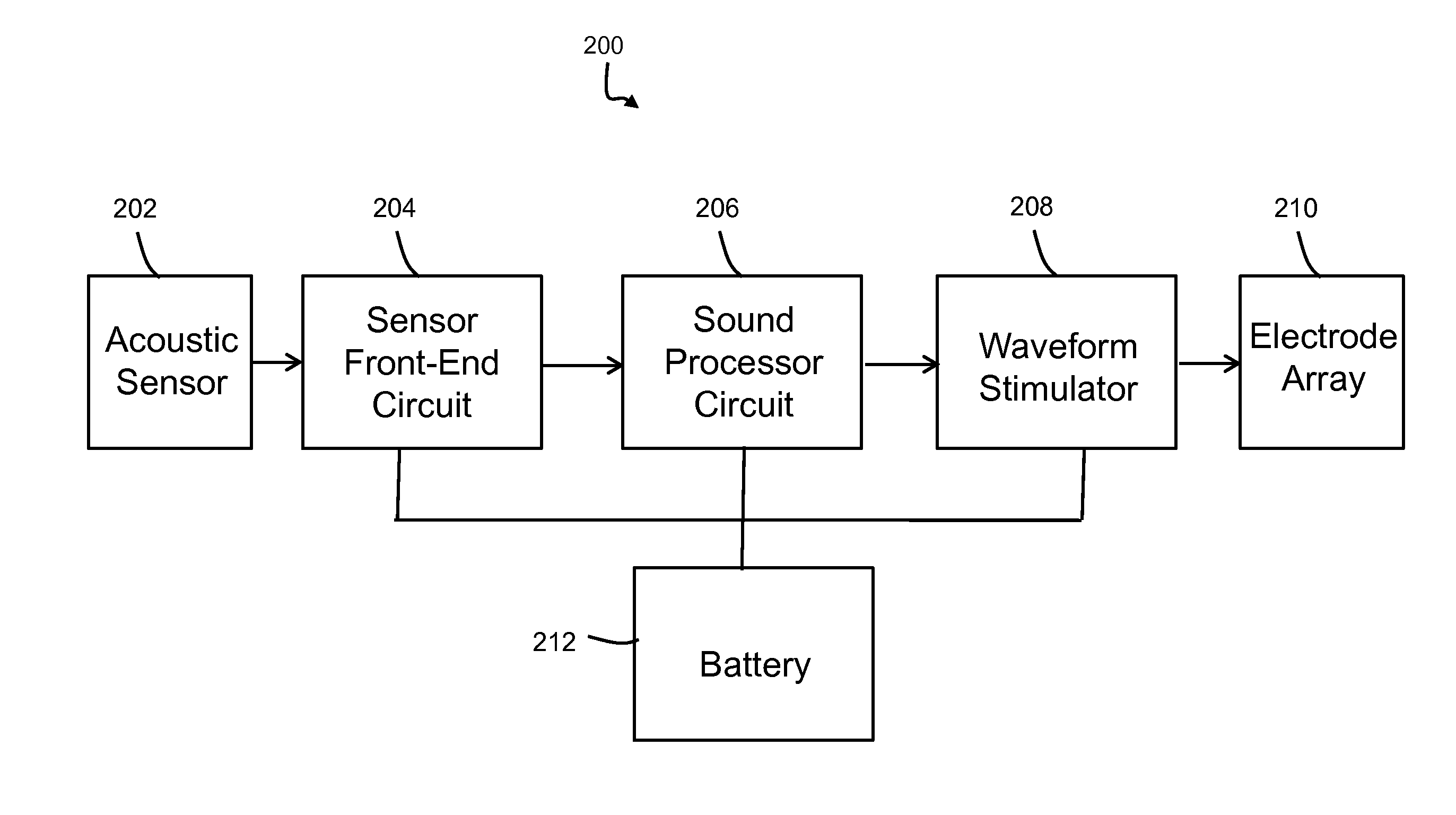
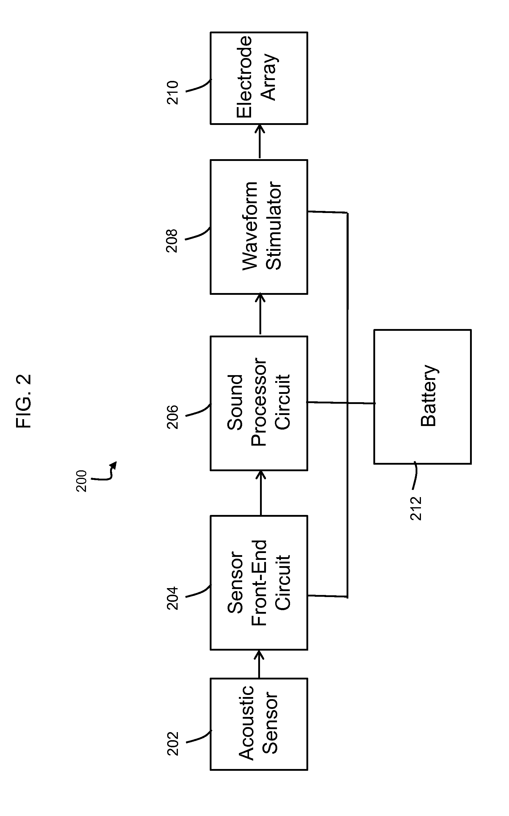
[0161]FIG. 12 shows an image 1200 of a manufactured fully-implantable cochlear implant chip. The chip has a size of 3.6 mm×3.6 mm while the active die area is 3.3 mm2 The chip was fabricated by 0.18 μm high-voltage CMOS technology and packaged in a 128-lead think quad flat package (QFP) package. The chip includes a sensor front-end circuit 1210, sound processor circuit 1230, waveform stimulator 1240, and SPI 1250. In this chip, ADC 1220 is located adjacent to sensor front-end circuit 1210. The sensor front-end circuit 1210 operated with a supply voltage of 1.5 V and the sound processor circuit 1230 operated with a supply voltage of 0.6 V. The ADC 1220 operated at a supply voltage of 0.6 V. The chip were reconfigurable to operate in 4-, 6-, 8-channel modes. Example specifications and power consumption of the chip are described in relation to Table 5-4 in U.S. Provisional Application 61 / 908,237 filed on Nov. 25, 2013, the entire contents of which are ...

example 2

Sound Processor Circuit

[0162]The sound processor circuit 1230 shown in FIG. 12 was tested using an arbitrary function generator (AFG3102 from Tektronix) to generate arbitrary test signals at the input of the ADC 1220. Outputs (dstimA[5:0] through dstimH[5:0]) of the sound processor circuit 1230 were recorded and reconstructed using a computer. All measurements with the ADC 1220 and sound processor circuit 1230 were made at a digital supply voltage of 0.6 V.

[0163]FIGS. 13A-D are images showing a demonstration the ability of the new systems to reconfigure the number of channels of the sound processor circuit 1230. A logarithmic chirp signal was input to the ADC 1220. FIG. 13A is a plot 1310 showing the measured spectrogram at the output of the ADC 1220. FIG. 13B is a plot 1320 showing the measured spectrogram of the sound processor circuit 1230 configured in a 4-channel mode. FIG. 13C is a plot 1330 showing the measured spectrogram of the sound processor circuit 1230 configured in a 6...

example 3

Waveform Stimulator

[0165]An electronic processor and waveform stimulator were used to generate a variety of waveforms by implementing a genetic algorithm. Several examples are described in this section.

[0166]Waveforms were generated over various phase widths. FIGS. 14A-C are plots of energy efficient waveforms for various pulse width. FIG. 14A is a plot 1410 showing the energy efficient waveform for pulse width of 25 μs. FIG. 14B is a plot 1420 showing the energy efficient waveform for pulse width of 50 μs. FIG. 14C is a plot 1430 showing the energy efficient waveform for pulse width of 100 μs. Each waveform in plots 1410-1430 are obtained with 10 steps / phase after 10,000 generations through a genetic algorithm. Phase widths can be generated, but not limited to, from 10 μs to 200 μs. The generated high efficiency waveforms are labeled as 1404 in all three plots. For comparison, a biphasic rectangular waveform at threshold for each of the corresponding phase widths are drawn and labe...


PUM


Abstract

In one aspect, the disclosure features systems for providing auditory signals to a subject. The systems include a sensor front-end circuit configured to be connected to an acoustic sensor and to convert analog signals received from the acoustic sensor to digital electric signals. The systems further include a sound processor circuit configured to be connected to the sensor front-end circuit and receive the electric signals provided by the sensor front end circuit. The sound processor includes multiple filters that spectrally decompose the received electrical signals into multiple spectral channels during operation of the system. The multiple spectral channels include at least a low frequency channel and a high frequency channel and the sound processor circuit is configured to operate the low frequency channel at a sample rate lower than a sample rate of the high frequency channel.

Description

CROSS REFERENCE TO RELATED APPLICATIONS[0001]This application claims priority from U.S. Provisional Application No. 61 / 908,237 filed on Nov. 25, 2013 and from U.S. Provisional Application No. 62 / 012,896 filed on Jun. 16, 2014, the entire contents of both of which are incorporated herein by reference.TECHNICAL FIELD[0002]This invention relates to cochlear implants.BACKGROUND[0003]Humans and other animals can suffer from conductive hearing loss, where there is damage to the ossicular chain (bones of the middle ear). Treatment options include medical or surgical treatment, or various types of hearing aids and prosthetics. Another form of hearing loss is sensorineural hearing loss, where there is damage to hair cells in the cochlea (inner ear). In this case, damage to the hair cells in the cochlea degrades the transduction of acoustic information to electrical impulses in the auditory nerve. Treatment options include hearing aids such as cochlear implants that are devices used to stimul...

Claims


Application Information

Patent Timeline
IPC IPC(8): A61N1/36A61N1/378A61N1/02
CPCA61N1/36032A61N1/378A61N1/025A61B2560/0219A61B5/6878A61B5/1114A61B2562/0204A61N1/36038
Inventor YIP, MARCUSCHANDRAKASAN, ANANTHASTANKOVIC, KONSTANTINA
Owner MASSACHUSETTS EYE & EAR INFARY
Why Eureka
Try Eureka