Active response gravity offload and method

Active Publication Date: 2015-11-24
NASA
View PDF45 Cites 37 Cited by
  • Summary
  • Abstract
  • Description
  • Claims
  • Application Information

AI Technical Summary

Benefits of technology

[0031]The method may further comprise providing that the horizontal control is operable to compensate for swinging of the cable induced by movement of a human load or other moving load mounted to the cable. In one embodiment, the horizontal control utilizes a Lyapunov-based function to minimize the swing energy.
[0032]In another embodiment, a three-dimensional simulator is provided that is operable for providing a selectable simulated gravity field for a load. The simulator may comprise non-limiting elements such as a carriage with a spool mounted for horizontal motion, a length of the cable extending downwardly from the spool, the cable being connectable to the load, a z-axis motor operably connected to the spool for controlling the length of the cable extending from the spool, and an x-axis motor and a y-axis motor operable to move the carriage in an x-axis direction and a y-a

Problems solved by technology

These systems may provide helpful results in certain ways but are limited in other ways.
The Reduced Gravity Simulator only allowed motion in one dimension and the pulleys were uncomfortable and were not able to support every part of the body.
POGO, although adding another dimension for motion, induced significant inertial loads on the users.
Also, the system did not match the dynamics of the person moving and limited their range of motion.
Some of the downsides to this method include: (1) limited space within the aircraft to move around, (2) simulated environments are only possible for 20-30 second intervals, (3) cost, and (4) the accuracy of the simulated gravity is dependent upon the precision in which the parabolas are flown.
While the first generation ARGOS system showed the concept is viable for use with a larger frame than used in the first generation ARGOS system, numerous problems were apparent for both the vertical and horizontal control systems that would potentially limit the realism of the simulation.
There are m

Method used


Image

  • Active response gravity offload and method
  • Active response gravity offload and method
  • Active response gravity offload and method

Examples


Embodiment Construction

[0052]Detailed descriptions of the preferred embodiment are provided herein. It is to be understood, however, that the present invention may be embodied in various forms. Therefore, specific details disclosed herein are not to be interpreted as limiting, but rather as a basis for the claims and as a representative basis for teaching one skilled in the art to employ the present invention in virtually any appropriately detailed system, structure or manner.

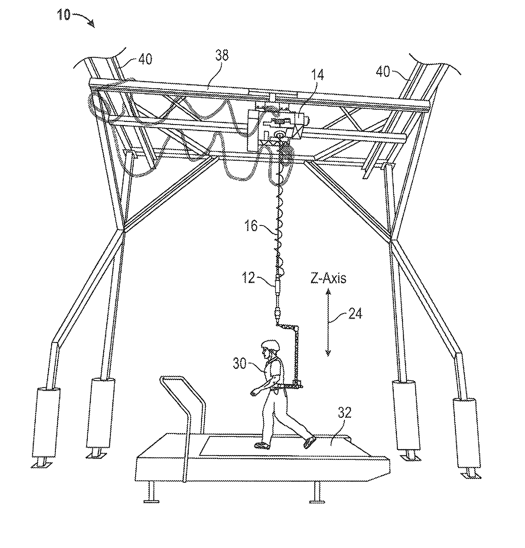
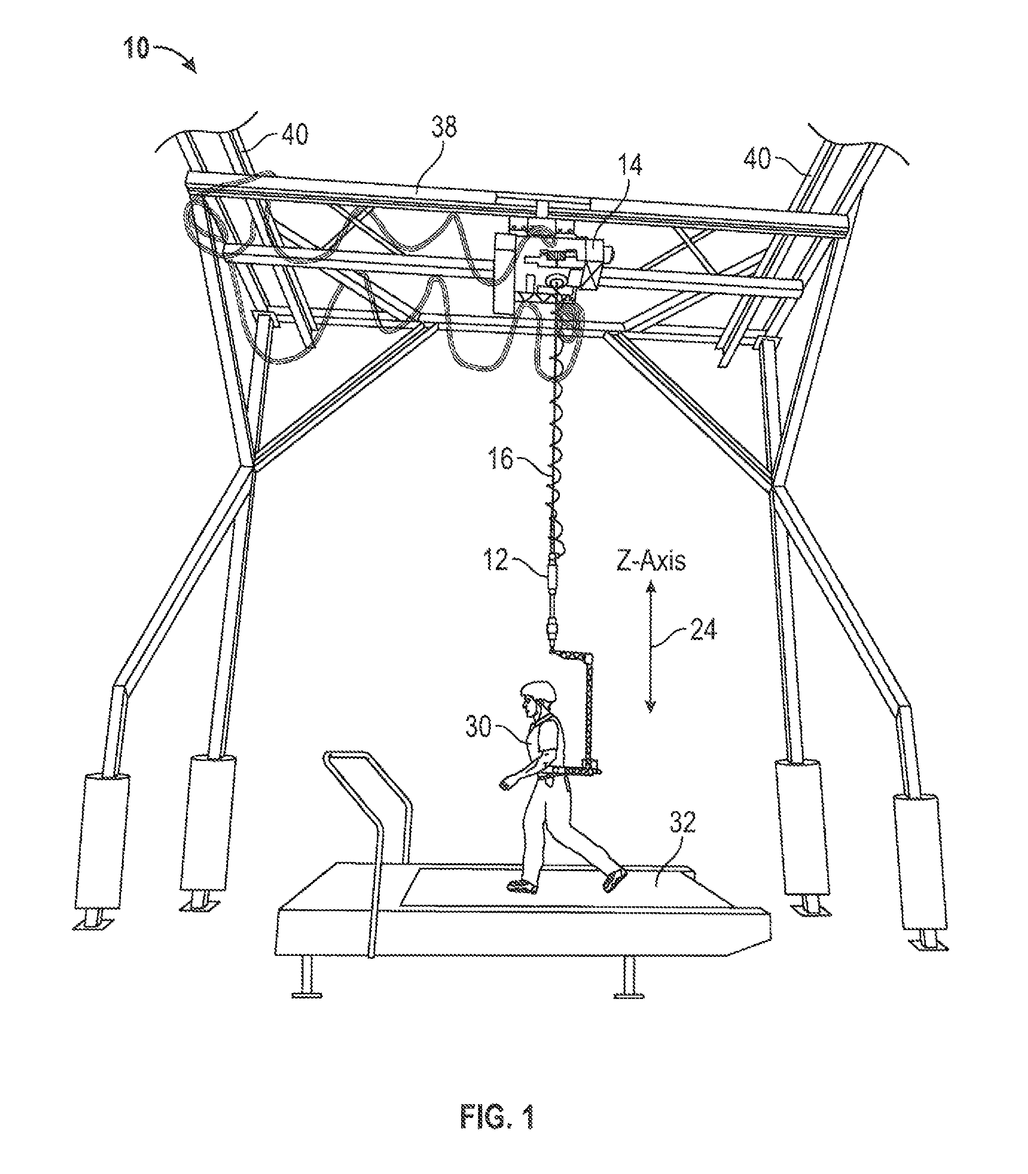
[0053]Referring now to FIG. 1, there is shown a human user or human load 30 supported by active response gravity offload system (ARGOS) 10 while on a treadmill 32. The human user may produce force vectors that the system should appropriately react to such as jumping or the like. The ARGOS facility 10 is designed to simulate any reduced gravity environment, such as Lunar, Martian, or microgravity. The ARGOS facility 10 uses inline load sensor or cell 12 in substantially vertical cable 16 to continuously offload of a selectable portion...


PUM


Abstract

A variable gravity field simulator can be utilized to provide three dimensional simulations for simulated gravity fields selectively ranging from Moon, Mars, and micro-gravity environments and/or other selectable gravity fields. The gravity field simulator utilizes a horizontally moveable carriage with a cable extending from a hoist. The cable can be attached to a load which experiences the effects of the simulated gravity environment. The load can be a human being or robot that makes movements that induce swinging of the cable whereby a horizontal control system reduces swinging energy. A vertical control system uses a non-linear feedback filter to remove noise from a load sensor that is in the same frequency range as signals from the load sensor.

Description

STATEMENT OF GOVERNMENT INTEREST[0001]The invention described herein was made by employee(s) of the United States Government and may be manufactured and used by or for the Government of the United States of America for governmental purposes without the payment of any royalties thereon or therefor.BACKGROUND OF THE INVENTION[0002]1. Field of the Invention[0003]The present invention relates generally to gravity simulation systems and, more specifically, to an active response gravity offload system and method for performing reduced gravity testing with robotic systems and humans.[0004]2. Background of the Invention[0005]Various types of reduced gravity or microgravity systems have been used in the past, some of which are discussed below. These systems may provide helpful results in certain ways but are limited in other ways.[0006]The National Aeronautics and Space Administration (NASA) has utilized a number of different types of gravity simulation systems. A Reduced Gravity Simulator u...

Claims


Application Information

Patent Timeline
IPC IPC(8): B64G7/00G01V7/00G01C1/00G01V13/00B66C13/06A63B69/00G01C25/00
CPCG01V7/00B66C13/06G01C1/00G01C25/00G01V13/00B64G7/00G01C15/105A63B69/0064A63B71/023A63B21/0058A63B21/151A63B21/153A63B22/02A63B24/0062A63B24/0075A63B24/0087A63B2024/0093A63B2071/027A63B2220/13A63B2220/16A63B2220/40A63B2220/803A63B2220/805A63B2244/08A63B2244/081A63B2244/087A63B21/00181
Inventor DUNGAN, LARRY K.VALLE, PAUL S.BANKIERIS, DEREK R.LIEBERMAN, ASHER P.REDDEN, LEESHY, CECIL
Owner NASA
Why Eureka
Try Eureka