

Driving method for electrophoretic displays
a technology of electrophoretic display and driving method, which is applied in the direction of instruments, electric digital data processing, computing, etc., can solve the problems of added costs and achieve the effect of low cos
- Summary
- Abstract
- Description
- Claims
- Application Information
AI Technical Summary
Benefits of technology
Problems solved by technology
Method used
Image

Examples
example 1
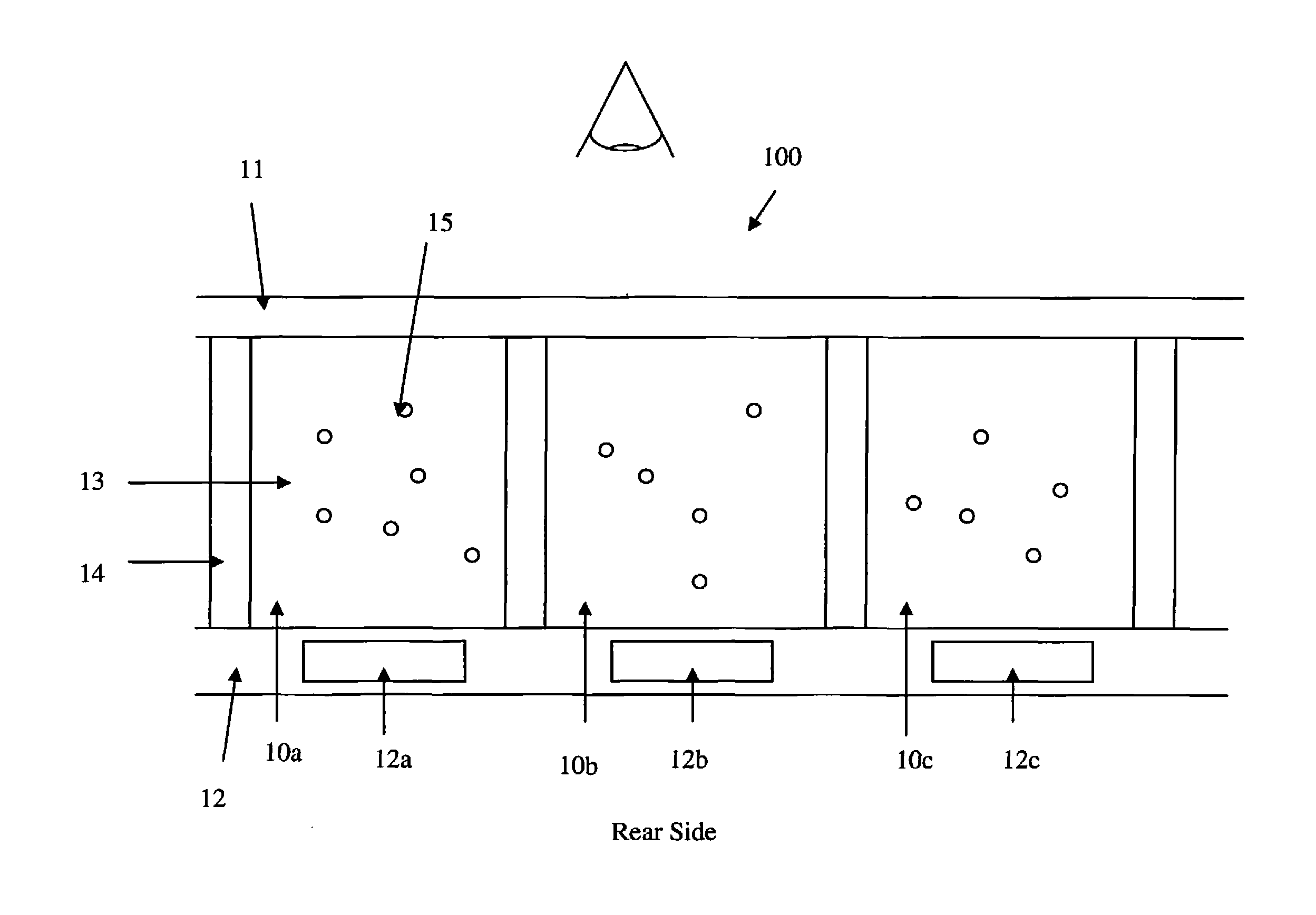
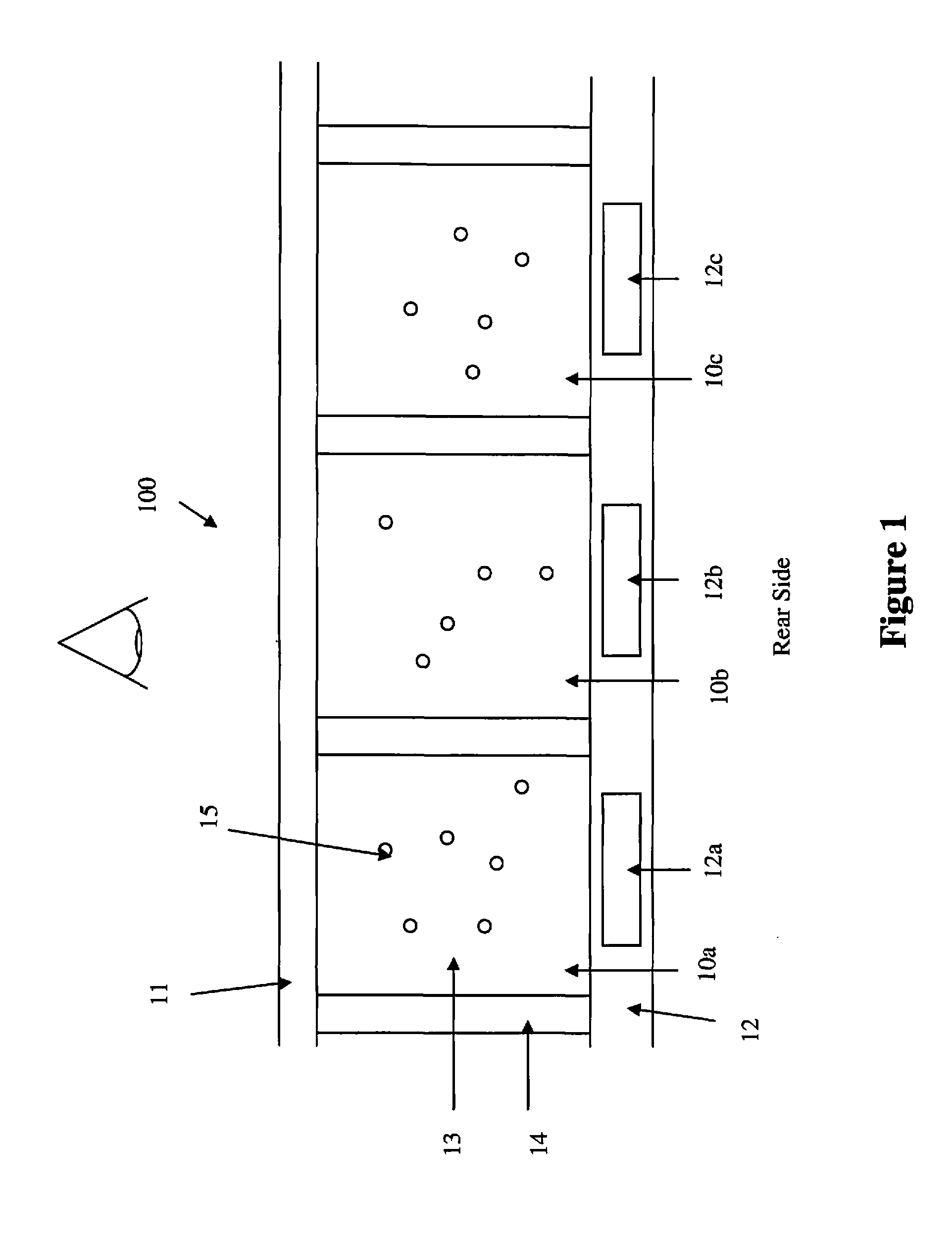
[0070]In order to illustrate the present driving method, it is assumed that the display cells are filled with an electrophoretic fluid comprising positively charged white particles dispersed in a black colored solvent, as shown in FIGS. 5a and 5b.
[0071]FIG. 3, as stated above, illustrates a single phase driving scheme.
[0072]When a driving voltage of +V is applied to a display cell, the display cell will display a white color state at the viewing side (see FIG. 5a). The initial color of the display cell may be black which will be driven to white after a driving voltage of +V is applied. If the initial color of the display cell is white, the display cell will remain in the white color state after a driving voltage of +V is applied.
[0073]When a driving voltage of −V is applied to a display cell, the display cell will display a black color state at the viewing side (see FIG. 5b). The initial color of the display cell may be white which will be driven to black after a driving voltage of...
example 2
[0077]It is further assumed that the final image display would have 80% white pixels and 20% black pixels. In other words, the 80% white / 20% black image is the target image to be achieved by the driving method, which is carried out in the following steps:
[0078]Step 1: Fifty percent (50%) of the pixels are driven to white and fifty percent (50%) of the pixels are driven to black. In other words, 50% of the pixel electrodes are applied a voltage of +V and 50% of the pixel electrodes are applied a voltage of −V (according to the waveforms of FIG. 3).
[0079]Consequently, Vcom may be calculated from the equation:
Vcom=(+V)×0.5+(−V)×0.5=0V
[0080]Step 2: The 50% of the white pixels achieved in step 1 would be kept white; thus no driving voltage being applied to those pixels in step 2. Among the 50% of the black pixels achieved in step 1, half of which (i.e., 25% of total) are applied a voltage of +V and the remaining half (i.e., 25% of total) would be applied a voltage of −V.
[0081]As a result...
example 3
[0088]This example illustrates the steps of Example 2 in a graphic manner. FIG. 6 shows an image consisting of 20 pixels, 1-20. FIG. 7c is the target image in which 80% of the pixels (1, 2, 4, 6-10, 12-15, 16 and 18-20) are white and 20% of the pixels (3, 5, 11 and 17) are black.
[0089]Following step 1 of Example 1, 50% of the pixels (4, 7, 9, 10, 13, 15, 16, 18, 19 and 20) are driven to white and the remaining 50% of the pixels (1, 2, 3, 5, 6, 8, 11, 12, 14 and 17) are driven to black to achieve an intermediate image as shown in FIG. 7a.
[0090]In step 2, the white pixels achieved in step 1 would be kept white. Among the black pixels achieved in step 1, half of which (2, 6, 8, 12 and 14) are driven to white and the remaining half (1, 3, 5, 11 and 17) are driven to black. The end result of step 2, as shown in FIG. 7b, is that 15 pixels (2, 4, 6-10, 12-15, 16 and 18-20) would be white and 5 pixels (1, 3, 5, 11 and 17) would be black.
[0091]In step 3, the white pixels achieved in steps 1...
PUM
 Abstract
Description
Claims
Application Information