Level-indicating scope mount

a level-indicating and scope technology, applied in the direction of weapon components, sighting devices, weapons, etc., can solve the problem of great care and attention

Active Publication Date: 2015-04-28
POWERS MICHAEL I
View PDF11 Cites 50 Cited by
  • Summary
  • Abstract
  • Description
  • Claims
  • Application Information

AI Technical Summary

Benefits of technology

[0015]The invention may be embodied as a scope mount for a rifle. Such a scope mount includes a level-vial incorporated as a conventionally non-removable element of the mount. A level-vial may conveniently be disposed in a socket formed in the proximal end of the mount and having a center-axis transverse to a length axis of the mount. Desirably, the socket is oriented to be horizontal when installed on a cooperating rifle, and the rifle is placed in a conventional horizontal shooting position. Such orientation inherently places the level-vial in a plumb condition to indicate any cant that might be present when the rife is ready to shoot. A rifle-contact interface of the mount is configured to automatically orient the level-vial with respect to a cooperatingly-structured rifle, simply by bolt-on attachment of the scope mount to the rifle. Desirably, a bubble element of the level-vial may be disposed for intersection by a vertical plane passing through the length axis when the rifle, on which the scope mount is installed, is disposed in a conventional horizontal shooting orientation, the bubble element then being disposed at a position to permit cheek-down observation by a shooter at an elevation between a scope affixed to the mount and the rifle. That is, the shooter is not required to raise his / her cheek from the rifle stock to observe the bubble. A wall portion of a workable socket includes a first opening through which a shooter may observe the bubble in the level-vial to visually obtain feedback regarding cant of the rifle.

Problems solved by technology

Such an arrangement undesirably positions the level-indicator in free space where the lever element is subject to damage from bumping into foreign objects.
However, great care must be taken when installing such a device, because the cap can be tightened down in an un-even fashion, and the gap between the top and bottom scope ring will allow the cap to be pulled out of plumb when tightening the cap-mounting screws.
Unfortunately, this requires another level placed on the bolt rails of the rifle to get the gun level, then plumbing the cross hair in the scope to a vertical plumb line to get the whole setup plumb and level.
The known prior art suffers by requiring a shooter to lift his / her head up from a conventional horizontal shooting position (raise his / her cheek from the rifle stock) to check the level to verify a proper shooting orientation of the system, just before pulling the trigger.

Method used


Image

  • Level-indicating scope mount
  • Level-indicating scope mount
  • Level-indicating scope mount

Examples


Embodiment Construction

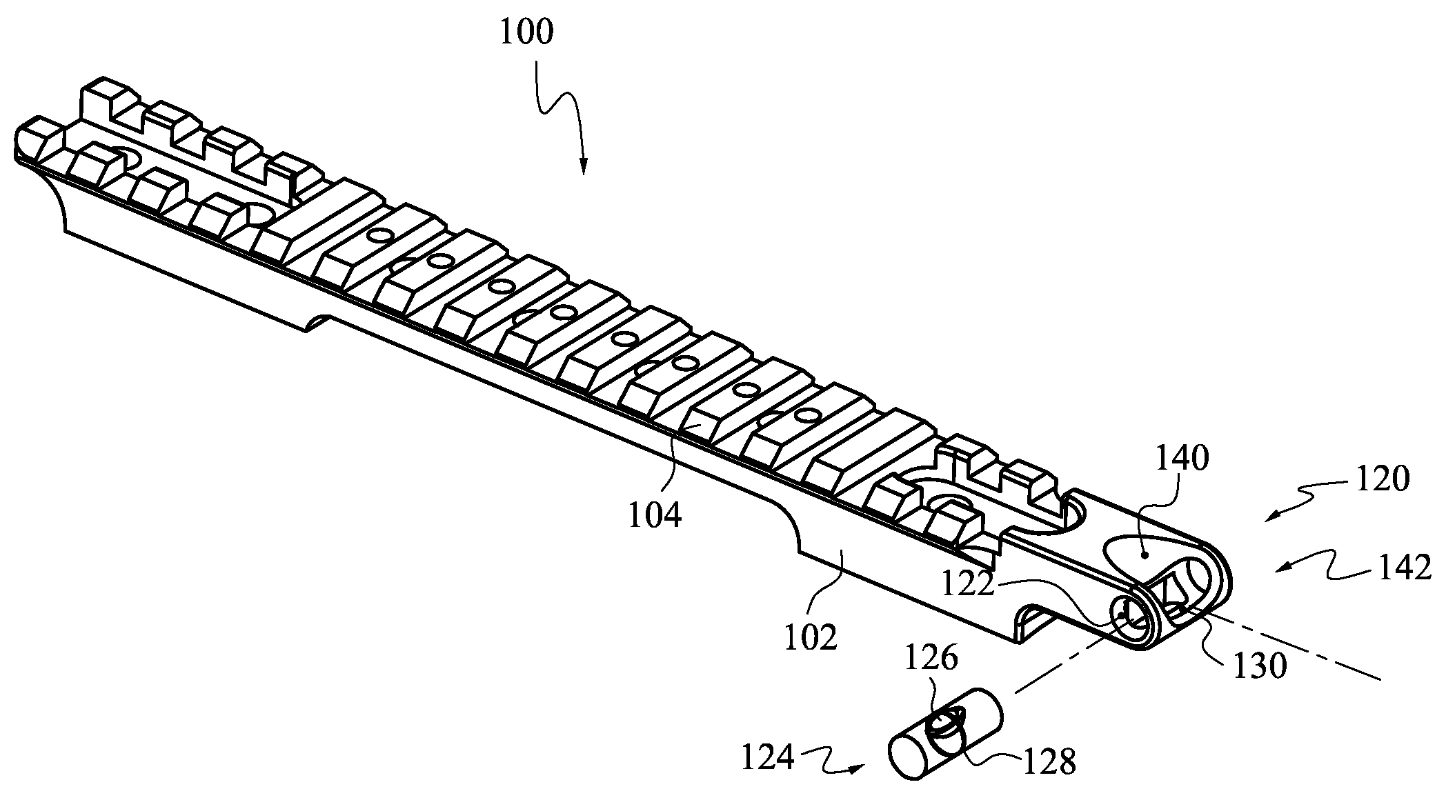
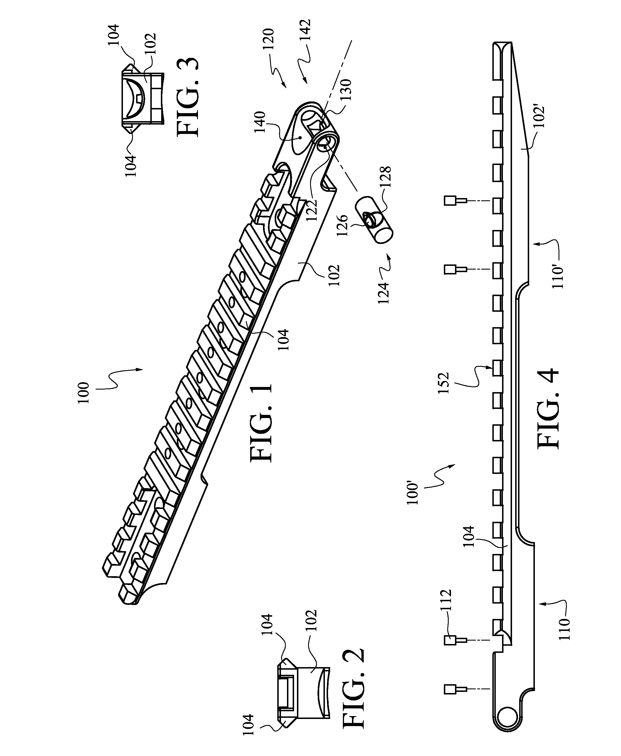
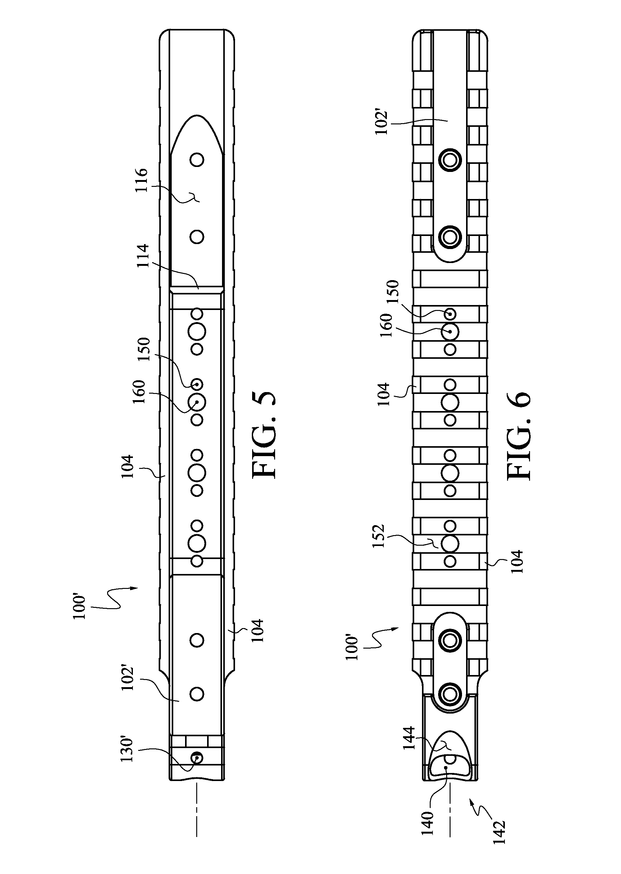
[0027]Reference will now be made to the drawings in which the various elements of the illustrated embodiments will be given numerical designations and in which the invention will be discussed so as to enable one skilled in the art to make and use the invention. Similar elements having different shapes may sometimes be indicated by the same numeral followed by a prime. It is to be understood that the following description is only exemplary of the principles of the present invention, and should not be viewed as narrowing the claims which follow.

[0028]An exemplary embodiment of a scope mount structured according to certain principles of the invention is illustrated generally at 100 in FIG. 1. Scope mount 100 is representative of a scope mount that may be characterized as a picatinny rail, certain characteristics of which are set forth in MIL-STD-1913 (AR) 3 Feb., 1995, which is hereby incorporated in its entirety as a portion of this disclosure by this reference. At the time of this wr...


PUM


Abstract

A fixture structured to attach a scope to a rifle. The fixture includes a level-vial that is visible by a shooter who is substantially at a conventional horizontal shooting position. In such position, the bubble element of the level-vial is disposed below the scope, and at a location that is intersected by a vertical plane containing the centerline of the rifle barrel.

Description

BACKGROUND[0001]1. Field of the Invention[0002]This invention relates to devices to indicate ballistic trajectories. Certain embodiments are particularly adapted for use to improve accuracy of bullet placement in long-range rifle shooting.[0003]2. State of the Art[0004]Accurate long-range shooting generally requires careful vertical alignment of a rifle barrel and sight system. A baseline trajectory typically assumes a projectile path is contained in a vertical plane. Conventionally, a sight element, such as a scope reticle, is placed into agreement with a vertical plumb line, and it remains up to the shooter to maintain that orientation when making a shot. Departure of the rifle and sight element from vertical agreement with the plumb line may be characterized as cant, which throws a projectile to either one side, or the other, as target range changes. The amount of undesired side travel of a projectile increases directly with increase in both range distance and cant angle.[0005]Va...

Claims


Application Information

Patent Timeline
Patent Type & Authority Patents(United States)
IPC IPC(8): F41G1/38F41G1/467F41G11/00
CPCF41G11/003F41G1/467F41G1/44
Inventor POWERS, JOHN D.
Owner POWERS MICHAEL I
Why Eureka
Try Eureka