Varying tissue compression with an anvil configuration

a tissue compression and configuration technology, applied in the field of surgical fastener application apparatus, can solve the problems of increased necrosis level, needless reduction of blood flow, and decreased time necessary to achieve hemostasis, so as to maximize the flow of blood and limit unnecessary necrosis

Active Publication Date: 2015-04-28
TYCO HEALTHCARE GRP LP
View PDF189 Cites 1075 Cited by
  • Summary
  • Abstract
  • Description
  • Claims
  • Application Information

AI Technical Summary

Benefits of technology

[0010]The present disclosure relates to surgical fastener applying apparatus that apply variable compression to tissue, and / or accommodate tissue of varying thickness. More specifically, surgical fastener applying apparatus in accordance with the principles of the present disclosure act to limit the flow of blood through tissue immediately adjacent a cut-line formed therein to effectuate hemostasis, while maximizing the flow of blood through tissue more removed from the cut-line to limit unnecessary necrosis.
[0018]The disclosed cartridge member includes a top wall having a plurality of retention slots formed therein that are configured and dimensioned to allow the surgical fasteners to pass therethrough during ejection from the cartridge member. Each fastener retention slot is aligned with a corresponding pocket formed in the tissue contacting surface of the anvil member. The fastener pockets formed in the tissue contacting surface of the anvil member may be arranged such that each fastener retention slot is aligned with a plurality of corresponding fastener pockets to reduce any likelihood of improper surgical fastener formation. In one embodiment, it is contemplated that the anvil member may be formed from a plurality of plates that are secured together.
[0019]The surgical fasteners are positioned within the cartridge member to define a predetermined distance between penetrating tips thereof and the corresponding pocket formed in the tissue contacting surface of the anvil member. The surgical fasteners positioned nearer to a centerline of the cartridge member may be shorter than the surgical fasteners positioned further from the centerline such that the distance defined between the penetrating tips of the surgical fasteners and the corresponding pockets formed in the tissue contacting surface of the anvil member varies with the distance between the surgical fasteners and the centerline of the cartridge member. For example, it is envisioned that the distance defined between the penetrating tips of the surgical fasteners and the corresponding pockets formed in the tissue contacting surface of the anvil member may increase with the distance between the surgical fasteners and the centerline of the cartridge member.

Problems solved by technology

It is commonly known that by increasing the amount of pressure applied to a wound, the flow of blood can be limited, thereby decreasing the time necessary to achieve hemostasis.
However, applying too much pressure can result in a needless reduction in blood flow to the tissue surrounding the cut-line, resulting in an elevated level of necrosis, a slower rate of healing, and / or a greater recovery period.
Additionally, when tissue is clamped and compressed between the anvil and cartridge, some of the fluid retained within the tissue is squeezed out, which results in greater compression at the portions of the cartridge and the anvil adjacent the cut-line when compared to the lateral edges.

Method used


Image

  • Varying tissue compression with an anvil configuration
  • Varying tissue compression with an anvil configuration
  • Varying tissue compression with an anvil configuration

Examples


Embodiment Construction

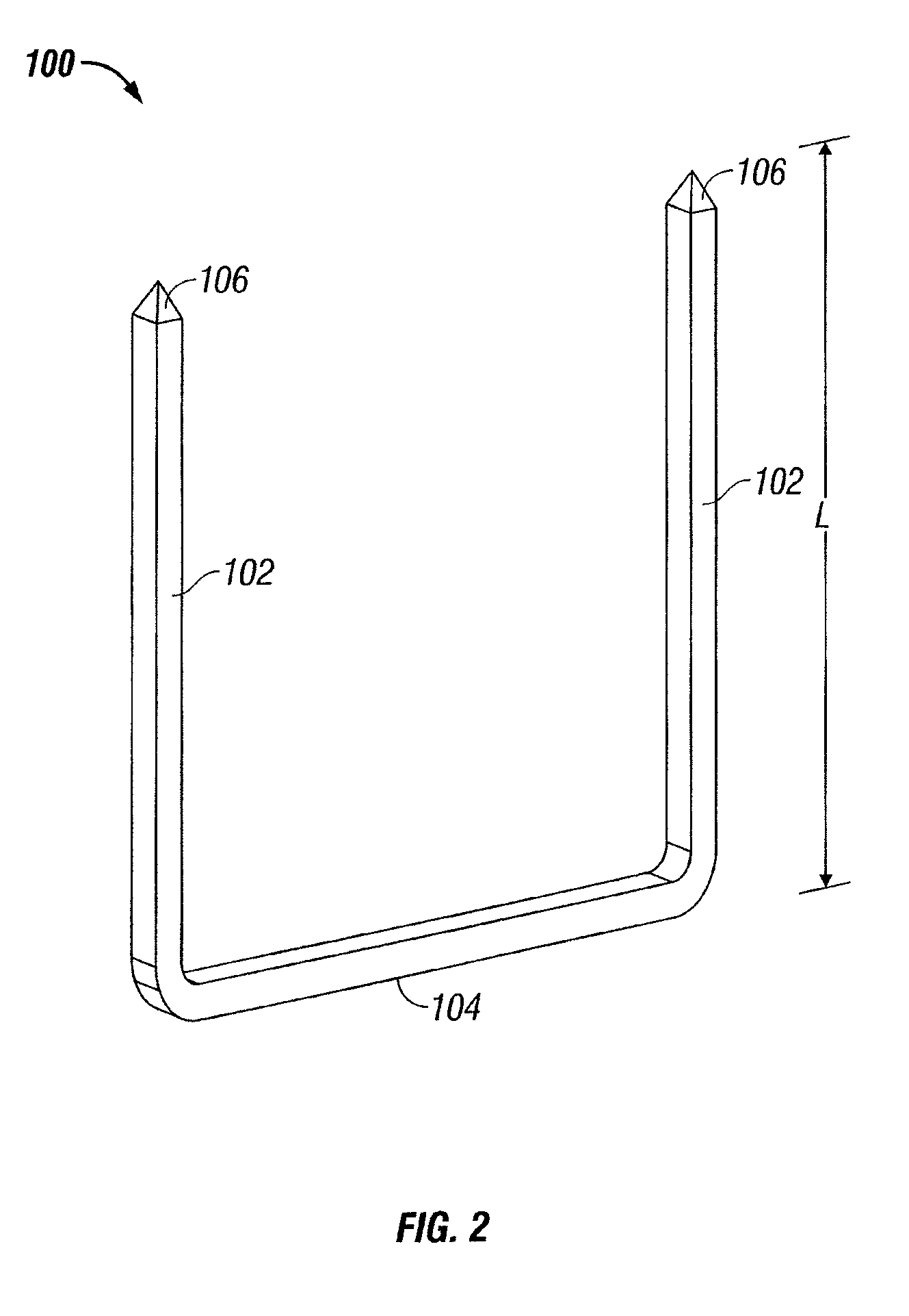
[0048]Various embodiments of the presently disclosed surgical fastener applying apparatus, and methods of using the same, will now be described in detail with reference to the drawings wherein like references characters identify similar or identical elements. In the drawings, and in the description which follows, the term “proximal” will refer to the end the surgical fastener applying apparatus, or component thereof, that is closest to the clinician during use, while the term “distal” will refer to the end that is furthest from the clinician, as is traditional and conventional in the art. In addition, the term “surgical fastener” should be understood to include any substantially rigid structure that is suitable for the intended purpose of joining tissue together, including but not being limited to surgical staples, clips, and the like.

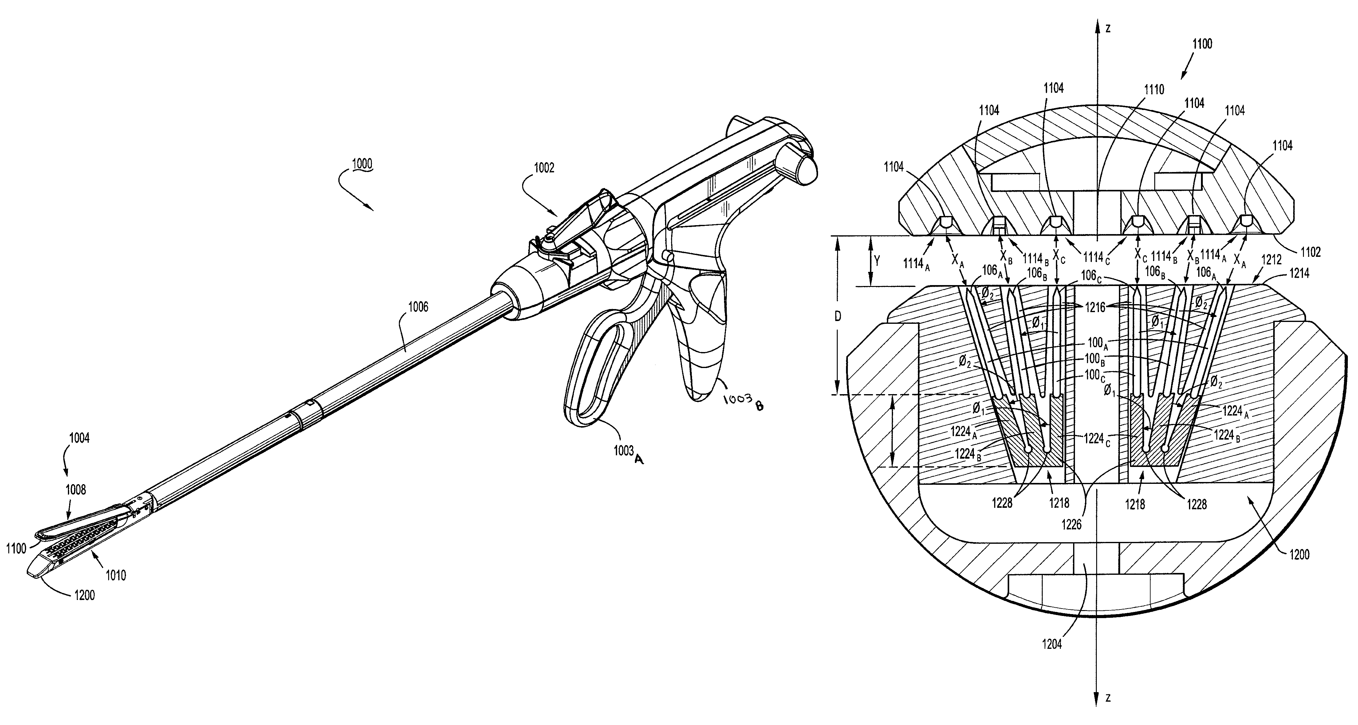
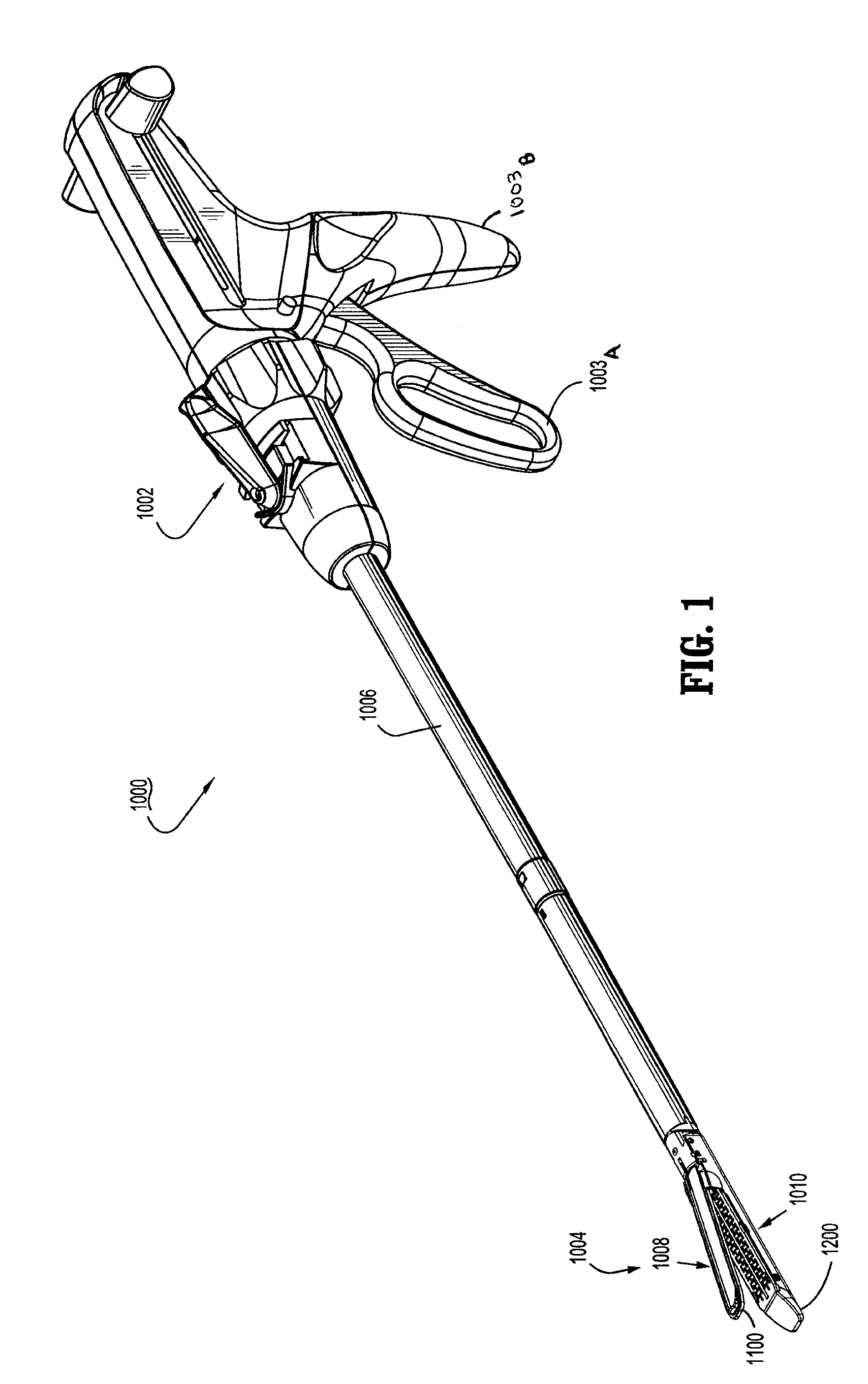
[0049]FIG. 1 illustrates a surgical fastener applying apparatus 1000, of either the re-usable or disposable variety, including a handle assembly 1002,...


PUM

PropertyMeasurementUnit
compressive forceaaaaaaaaaa
compressive forcesaaaaaaaaaa
lengthaaaaaaaaaa

Abstract

The present disclosure relates to surgical fastener applying apparatus and the application of variable compression to tissue. More specifically, the presently disclosed surgical fastener applying apparatus act to limit the flow of blood through tissue immediately adjacent a cut-line formed therein to effectuate hemostasis, while maximizing the flow of blood through tissue more removed from the cut-line to limit unnecessary necrosis. In one embodiment, a surgical fastener applying apparatus is disclosed having a tool assembly coupled to a distal end thereof with first and second jaws respectively including an anvil and a surgical fastener cartridge. The surgical fastener cartridge includes, among other things, angled pushers that engage surgical fasteners of varying lengths.

Description

CROSS-REFERENCE TO RELATED APPLICATIONS[0001]This application claims the benefit of, and priority to, U.S. Provisional Pat. Application Ser. No. 61 / 051,916, filed May 9, 2008, the entire contents of which are incorporated by reference herein.BACKGROUND[0002]1. Technical Field[0003]The present disclosure relates to surgical fastener applying apparatus. More particularly, the present disclosure relates to a tool assembly for use with a surgical fastener applying apparatus, and methods of manufacturing the same, to apply a plurality of surgical fasteners to tissue with varying compressive forces.[0004]2. Background of the Related Art[0005]Many varieties of surgical fastener applying apparatus are known in the art, some of which are specifically adapted for use in various surgical procedures including, but not limited to, end-to-end anastomosis, circular end-to-end anastomosis, open gastrointestinal anastomosis, endoscopic gastrointestinal anastomosis, and transverse anastomosis. Suitab...

Claims


Application Information

Patent Timeline
Patent Type & Authority Patents(United States)
IPC IPC(8): A61B17/04A61B17/10A61B17/072
CPCA61B17/072A61B2017/07214A61B2017/07235A61B2017/07242A61B2017/07264A61B2017/07278A61B17/068A61B17/105
Inventor VIOLAZEMLOK, MICHAEL
Owner TYCO HEALTHCARE GRP LP
Why Eureka
Try Eureka