Venous Augmentation System

a technology of venous augmentation and stent, which is applied in the field of venous augmentation systems, can solve the problems of thrombosis formation and inherent shortcomings, and achieve the effect of reducing pressure in the chamber and facilitating blood flow

Active Publication Date: 2011-09-15
KPR U S LLC
View PDF16 Cites 14 Cited by
  • Summary
  • Abstract
  • Description
  • Claims
  • Application Information

AI Technical Summary

Benefits of technology

[0005]In one aspect, a method for augmenting blood flow in a limb that is wrapped with a sleeve having at least one chamber capable of being pressurized for applying compression to the limb in a region generally underlying the chamber generally comprises pressurizing the chamber to a first compression pressure to move blood in the limb from the region generally underlying the chamber. After pressurizing said at least one chamber to the first compression pressure, pressure in the chamber is reduced to a refill pressure to allow blood to reenter the region of the limb generally underlying the chamber. Pressure in the chamber is then sensed to determine a first venous refill time corresponding to an elapsed amount of time for venous blood flow in the limb to return to a steady state. The first three steps are repeated a second and other times using second and other compression pressures that are different from the first compression pressure and from each other. Second and other venous refill times are then determined. A customized compression pressure is determined by locating the compression pressure at which blood flow out of the region generally underlying the chamber is maximized by finding compression pressure at a maximum venous refill time. Compression therapy is applied to the limb with the sleeve including repeatedly pressurizing the chamber to the customized compression pressure and reducing pressure in the chamber.

Problems solved by technology

Stasis is problematic because it is a significant cause leading to the formation of thrombi.
However, due to the variability in patient's extremities, these devices have inherent shortcomings.

Method used


Image

  • Venous Augmentation System
  • Venous Augmentation System
  • Venous Augmentation System

Examples


Embodiment Construction

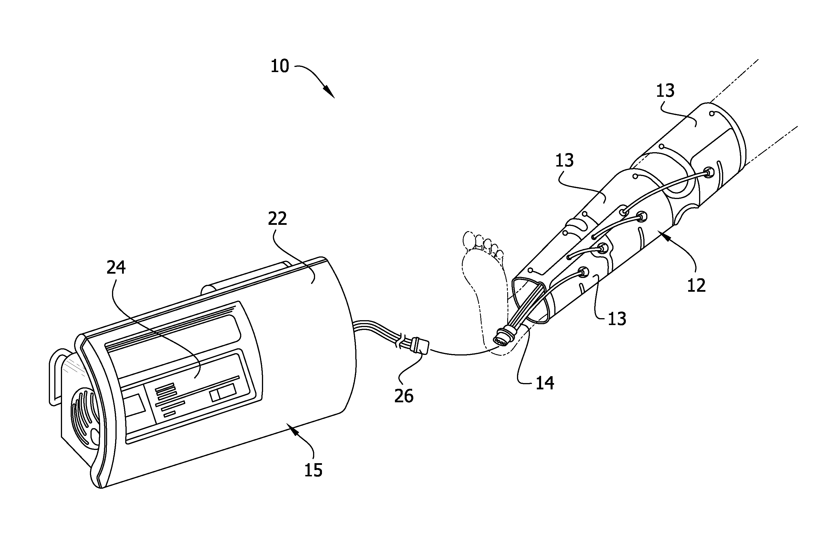
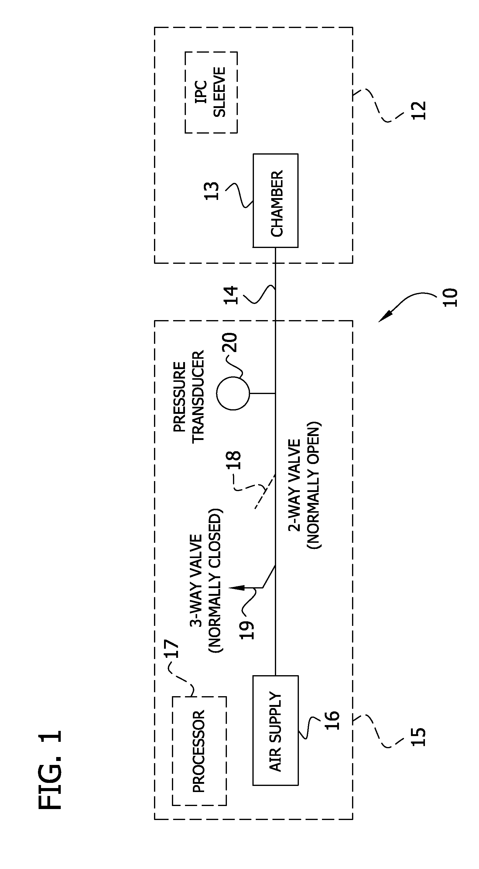
[0017]With reference to the figures, FIG. 1 in particular illustrates a pneumatic circuit in association with an intermittent pneumatic compression (IPC) device 10 to determine venous refill time according to the present invention. In the IPC device 10, a compression sleeve 12 having a single chamber 13 is connected, for example, via tubing 14, to a controller 15 having a processor 17 operatively connected to an air supply 16 (e.g., a compressor) which provides compressed air to the chamber of the sleeve. A two-way normally open valve 18 and a three-way normally closed valve 19 are provided between the sleeve 12 and the air supply 16. A pressure transducer 20 downstream of the valve 18 monitors the pressure in the chamber. The sleeve 12 can have two or more chambers without departing from the scope of the invention. For example, the sleeve 12 shown in FIG. 6 has three chambers 13.

[0018]The sleeve 12 is configured to be wrapped around a patient's extremity (e.g., leg) (FIG. 6). To pr...


PUM


Abstract

A method for augmenting blood flow in a limb that is wrapped with a sleeve having at least one chamber for applying compression to the limb in a region generally underlying the chamber includes pressurizing the chamber to a first compression pressure and then reducing the pressure to a refill pressure. Pressure in the chamber is then sensed to determine a first venous refill time. The preceding steps are repeated a second and other times using second and other compression pressures that are different from the first compression pressure and from each other to determine second and other venous refill times. A customized compression pressure is determined by locating the compression pressure at which blood flow out of the region generally underlying the chamber is maximized by finding compression pressure at a maximum venous refill time. A compression device employing such a method is also disclosed.

Description

FIELD OF THE INVENTION[0001]The present invention generally relates to compression sleeves, and more particularly, compression sleeves for optimizing vascular refill.BACKGROUND OF THE INVENTION[0002]The pooling of blood or stasis in a patient's extremities, particularly the legs, occurs when the patient is confined to bed for an extended period of time. Stasis is problematic because it is a significant cause leading to the formation of thrombi. To prevent this occurrence, it is desirable to move fluid out of interstitial spaces in the extremity tissues to enhance circulation.[0003]Intermittent pneumatic compression (IPC) devices are used to improve circulation and minimize the formation of thrombi in the limbs of patients. An example of one such IPC device is disclosed in U.S. Pat. No. 6,231,53. These devices typically include a compression sleeve or garment having one or more inflatable chambers configured to provide a compressive pulse to the limb. The chamber or chambers are main...

Claims


Application Information

Patent Timeline
Patent Type & Authority Applications(United States)
IPC IPC(8): A61H7/00A61B17/00
CPCA61H9/0078A61H2205/10A61H2205/06A61H2201/5071A61H7/00A61H9/00A61H23/04
Inventor BOCK, MALCOLM G.
Owner KPR U S LLC
Why Eureka
Try Eureka