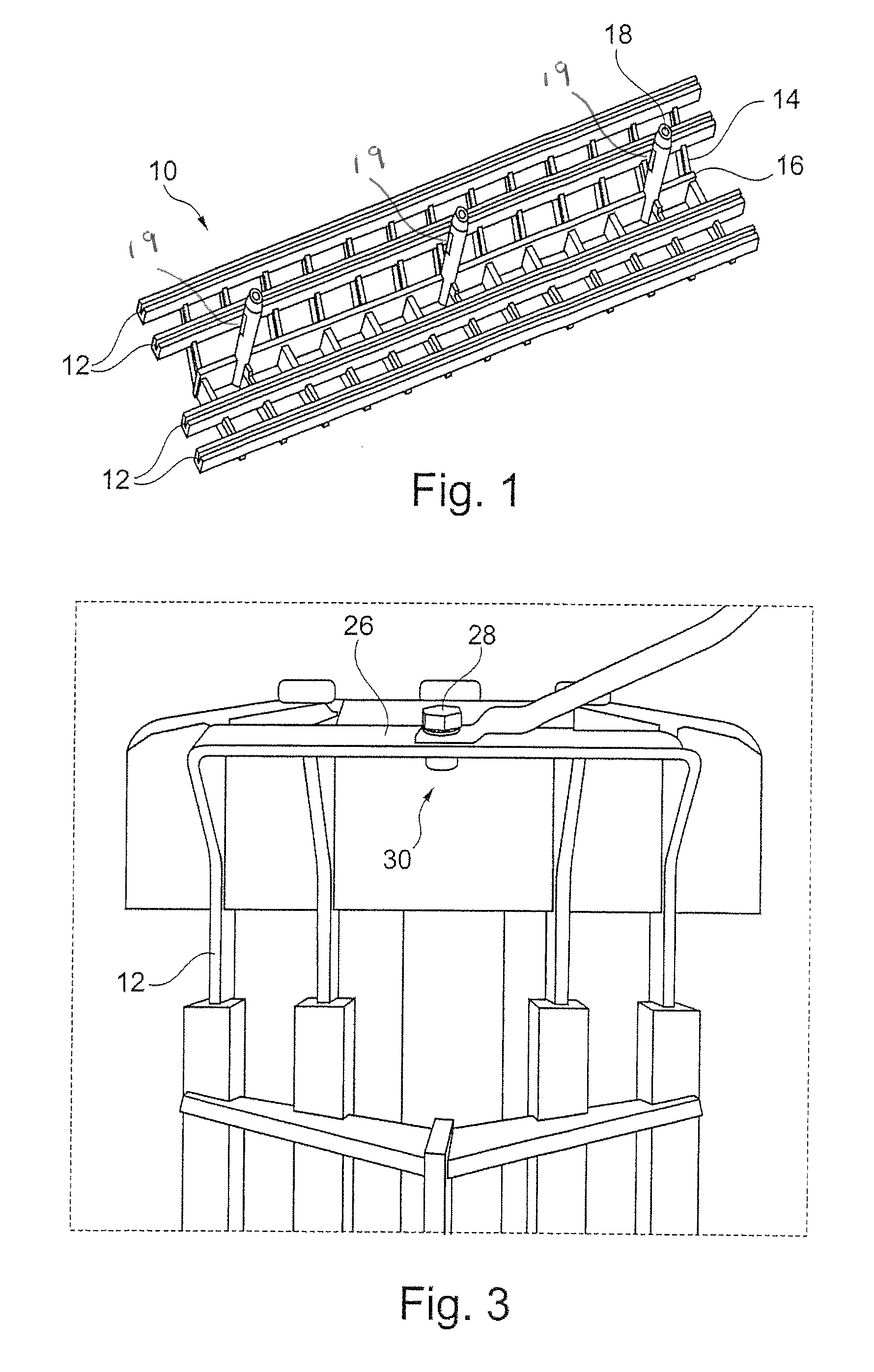
[0007]Consequently, the tool according to the invention has at least one cover, to which a thief cathode is attached. In other words, the thief cathode is integrated into the cover, which leads to the particular advantages that the thief cathode can be removed during the process. This is different from the cathodes used hitherto, which are fixed in the tool. The possibility of removing the thief cathode during the coating process offers the following advantage. After the “main” coating, the running surface is conventionally provided with a binary or ternary lead-free sliding layer. The steel backing must subsequently be provided with a so-called flash. This flash, which is based, for example, on tin, serves as corrosion protection and is to be applied primarily to the steel bearing backing in order to protect the highly reactive steel from oxidation in the air (rust). This corrosion protection is accordingly to be applied primarily to the bearing backing. However, that region is not coated in the presence of the thief cathode. Consequently, while the current, in the context of the main coating, is passed over a resistor of, for example, from 0.001 ohm to 0.02 ohm, in particular from 0.003 ohm to 0.0095 ohm, before being passed to the bearing shells to be coated, in order to produce a potential difference between the thief cathode and the bearing shells, in order to prevent coating on the backing, that potential difference is eliminated by the removal of the thief cathode and the bearing backings can advantageously be provided with the desired corrosion protection.
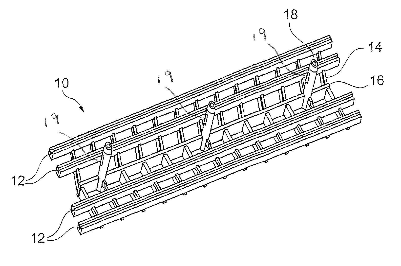
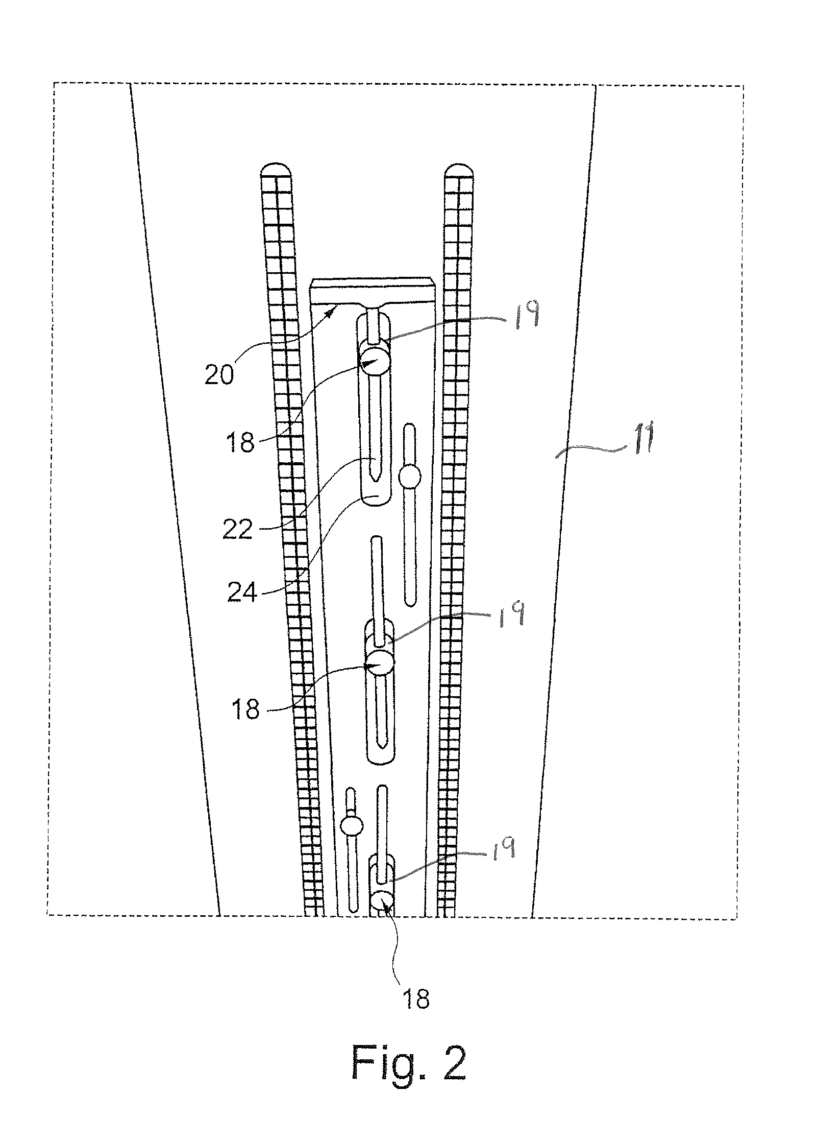
[0008]Preferably, the tool according to the invention further has at least one holder, which is characterised in that it has at least one bar suitable for mechanically fixing and / or electrically contacting a plurality of bearing shells. By means of the mechanical fixing, optionally in conjunction with a section, for example a wall of the tool, the column of bearing shells is prevented from caving in. The holder presses the column of bearing shells against a wall of the tool, for example, by means of the at least one bar, so that there is a substantially lower risk of the column of bearing shells caving in, collapsing of the column of bearing shells is eliminated, and coating of the dividing face is avoided. The proportion of rejects is markedly reduced as a result. In particular, it has been possible to establish in initial tests that the rejects resulting from collapsed bearing shells can be reduced to zero. Furthermore, undesirable coating of the dividing faces can be prevented by the pressing against the tool wall.
[0009]By the contacting of a plurality of bearing shells on their respective backings, a plurality, preferably all, of the bearing shells to be coated are contacted by the holder according to the invention. The resistance within the column of bearing shells is thereby reduced, and the sliding surface of the bearing shell can be coated with a markedly reduced variation in the coating thickness. In particular, it has been found that the variation within a column of bearing shells with the holder according to the invention is only approximately from 2 μm to 3 μm and coating of the dividing face is avoided, while in the procedure used hitherto, in which only the end faces of the column of bearing shells were contacted, a variation of from 6 μm to 7 μm occurred and the dividing face was coated with up to 20 μm. Accordingly, it was possible to reduce markedly the rejects due to significant variation. On account of its function, the described holder can also be referred to as backing contacting. This constitutes an independent aspect of the present application, which develops its advantages independently of the features described hereinabove or hereinbelow but can be combined therewith.
[0010]In particular for stability with regard to the mechanical fixing, a plurality, in particular an even number, of largely parallel bars has been found to be advantageous. Together with the pressing against a wall of the tool, it is possible, for example, with two parallel bars to create a statically determinate fixing. Furthermore, it is advantageous for the efficiency of the coating of a plurality of in particular comparatively small bearing shells for two or more bearing shell columns to be erected side by side, which means an even number of largely parallel bars for a mechanically advantageous fixing. It will be appreciated that it is possible for only two or three such bars to be present in order to electrically contact and mechanically fix a single column of bearing shells. This can be provided, for example, in the case of comparatively large bearing shells. Furthermore, it is conceivable in principle to provide such a holder for more than two columns of bearing shells. A holder for two columns of bearing shells has been found to be successful, for example, for bearing shells having a diameter of from 28 mm to 70 mm, while for larger bearing shells a holder for a single bearing shell can be provided.
[0012]For the performance of the tasks required of the holder, it is advantageous if the holder can be fixed and preferably braced in the tool. In particular, bracing can be carried out in such a manner that the bearing backings are particularly well contacted and / or the dividing faces of the bearing shells are pressed particularly firmly against a wall of the tool, so that coating here is advantageously prevented.
[0013]The tool according to the invention preferably further has at least one plastics block, which is arranged above the columns of bearing shells in order to ensure, in particular at the upper end of the column of bearing shells, that all the bearing shells are located beneath the surface of the electrolyte bath and are reliably coated. The dummy shell at the bottom is not necessary, which results in an increase in productivity.

