Waste heat utilization device and operating method

a technology of waste heat and operating method, which is applied in the direction of steam engine plants, mechanical equipment, machines/engines, etc., can solve the problems of inability to drop the pressure in the working medium during cooling to ambient temperature, and achieve the effects of reducing equipment complexity, high pressure, and relatively easy control

Active Publication Date: 2015-05-05
DAIMLER AG
View PDF13 Cites 8 Cited by
  • Summary
  • Abstract
  • Description
  • Claims
  • Application Information

AI Technical Summary

Benefits of technology

[0013]The pressure store may be designed as a spring-loaded store in which a stored volume is pre-tensioned to the minimum pressure by means of an elastic force. The pressure store may thus be implemented particularly easily and inexpensively, preferably as a passive pressure store. In principle, for this type of spring-loaded pressure store it is possible to configure the elastic force so as to be adjustable in that the spring-loaded pressure store may also be implemented as an active spring-loaded pressure store. This is because the minimum pressure as well may be varied or set by means of the adjustable elastic force.
[0016]In one particularly advantageous embodiment, a minimum pressure of at least 500 mbar, preferably at least 600 mbar, is set or ensured in the working medium in a cold state of the waste heat utilization device which is cooled to ambient temperature. Such small negative pressures with respect to 1 bar ambient pressure may be controlled comparatively easily, which reduces the complexity of equipment for implementing the waste heat utilization device.
[0017]According to another advantageous embodiment, it may be provided that for transient operating states of the waste heat utilization device, the high pressure is regulated and / or controlled during hot operation of the waste heat utilization device with the aid of the active pressure store. Transient operating states of the waste heat utilization device may arise when the heat dissipation potential of the heat source that is used changes. The internal combustion engine generally constitutes the heat source. In particular, an exhaust system of the internal combustion engine is preferred as a heat source, since a comparatively large quantity of waste heat is available there for further utilization. If the operating state of the internal combustion engine changes with regard to load and / or speed, the temperature, pressure, and volumetric flow in the exhaust gas, i.e., the heat transported in the exhaust gas, also change in real time. If the heat that is transferable to the working medium in the evaporator changes, the evaporative capacity of the evaporator also changes, which results in mass displacement of the working medium between the liquid phase and the gas phase within the waste heat utilization circuit, and ultimately influences the high pressure in the waste heat utilization circuit. Since the waste heat utilization device is usually designed for optimal high pressures for a certain nominal operating state having a relatively narrow pressure range, a greatly varying high pressure which drops from the desired high pressure interval reduces the efficiency of the waste heat utilization device. By making use of the pressure store that is present in the waste heat utilization device according to the invention for controlling or regulating the high pressure, in such transient operating states it may be ensured comparatively easily that the high pressure of the waste heat utilization circuit remains within the predetermined high pressure interval, so that the waste heat utilization device operates within its optimized nominal operation, and thus at optimal efficiency.
[0018]According to another advantageous embodiment, the pressure store is activatable and deactivatable by means of a valve device, for example. In the activated state the pressure store is fluidly coupled to the waste heat utilization circuit, so that working medium may flow from the pressure store into the waste heat utilization circuit and back. In the deactivated state the pressure store is fluidly decoupled from the waste heat utilization circuit, so that no exchange of working medium is possible between the pressure store and the waste heat utilization circuit. Due to the possibility of activating and deactivating the pressure store, the waste heat utilization device, depending on its design, may be operated in an optimal manner in hot operation without having to take into account the additional working medium stored in the pressure store. This results in particularly simple handling and design.

Problems solved by technology

As a result, the pressure in the working medium during cooling to ambient temperature is not able to drop as greatly as would be the case for a circuit with a constant volume or a constant mass of the working medium.

Method used


Image

  • Waste heat utilization device and operating method
  • Waste heat utilization device and operating method
  • Waste heat utilization device and operating method

Examples


Embodiment Construction

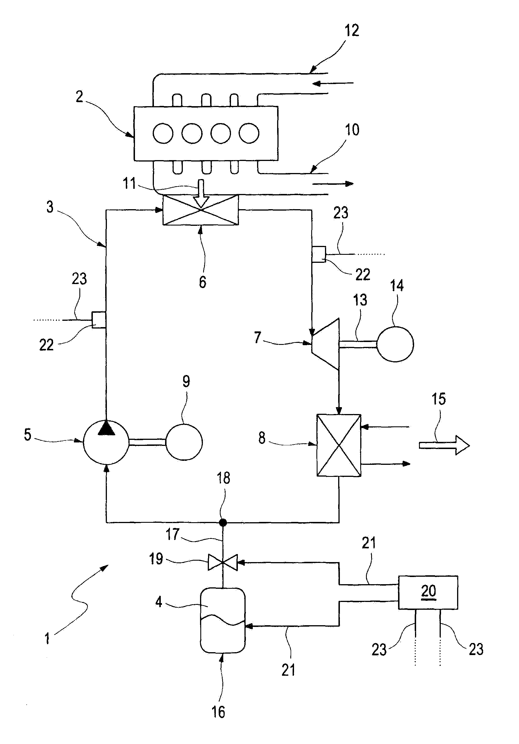
[0022]According to FIG. 1, a waste heat utilization device 1 which together with an internal combustion engine 2 may be situated in a motor vehicle includes a waste heat utilization circuit 3 in which a working medium 4 circulates. The waste heat utilization circuit 3 is preferably designed as a closed circuit. The waste heat utilization device 1 also includes a pumping device 5, an evaporator 6, an expansion machine 7, and a condenser 8.

[0023]The pumping device 5 is situated in the waste heat utilization circuit 3, and is used for pressurizing the working medium 4 to a high pressure. The pumping device 5 is advantageously designed as a volumetric pump, and for this purpose is drive-coupled to a drive motor 9. The evaporator 6 is situated in the waste heat utilization circuit 3, downstream from the conveying device 5, and is used for evaporating the pressurized working medium 4, for which purpose the evaporator 6 utilizes waste heat from the internal combustion engine 2. To this end...


PUM


Abstract

In a waste heat utilization arrangement for an internal combustion engine of a motor vehicle including a waste heat utilization circuit in which a working medium is circulated, a pumping device for pressurizing the working medium, an evaporator for vaporizing the working medium by waste heat of the internal combustion engine, an expansion machine for expanding the working medium while extracting mechanical energy therefrom and a condenser for condensing the working medium in a resting state, the waste heat utilization circuit is in communication with a pressure store capable of maintaining a pressure for setting and ensuring a predetermined adjustable minimum pressure of the working medium in the waste heat utilization circuit.

Description

[0001]This is a Continuation-In-Part application of pending international patent application PCT / EP2011 / 006039 filed Dec. 2, 2011 and claiming the priority of German patent application 10 2010 054 733.6 filed Dec. 16, 2010.BACKGROUND OF THE INVENTION[0002]The present invention relates to a waste heat utilization device for an internal combustion engine, in particular of a motor vehicle having a waste heat utilization circuit. The invention further relates to an associated operating method.[0003]A waste heat utilization device is known from JP 2006-349211 A which operates according to the Rankine cyclic process or according to the Rankine Clausius process. This type of waste heat utilization device includes a waste heat utilization circuit in which a working medium circulates, a conveying device, situated in the waste heat utilization circuit for conveying the working medium against a high pressure, an evaporator situated in the waste heat utilization circuit downstream of the convey...

Claims


Application Information

Patent Timeline
Patent Type & Authority Patents(United States)
IPC IPC(8): F02G3/00F01K13/02F01K23/06F01N5/02F02G5/02
CPCF01N5/02F01K13/02F01K23/065F02G5/02Y02T10/166Y02T10/12
Inventor GAERTNER, JANKOCH, THOMAS
Owner DAIMLER AG
Why Eureka
Try Eureka