Outdoor unit for air conditioner

a technology for outdoor units and air conditioners, which is applied in the field of outdoor units for air conditioners, can solve the problems of affecting the operation performance of outdoor units and foreign substances entering the inside of outdoor units, and achieve the effect of beautiful design of outdoor units and preventing foreign substances

Active Publication Date: 2015-05-05
LG ELECTRONICS INC
View PDF18 Cites 3 Cited by
  • Summary
  • Abstract
  • Description
  • Claims
  • Application Information

AI Technical Summary

Benefits of technology

[0013]First, since the discharge port of the outdoor unit is opened only when operating the outdoor unit, the introduction of the foreign substance may be prevented via the discharge port when not operating the outdoor unit.
[0014]Further, when the discharge port of the outdoor unit is selectively closed by the louvers and the louvers close the discharge port of the outdoor unit, an advertisement or a picture may be attached to the surface of the louver, such that there is an advantage that may beautifully design a shape of the outdoor unit. In other words, there is a advantage that may use the front of the outdoor unit as an advertising board.

Problems solved by technology

Since the discharge port of an existing outdoor unit is maintained in opened condition regardless of whether or not the operation of the outdoor, when the outdoor unit is not operating, there is a disadvantage that the foreign substance is introduced into the inside of the outdoor unit via the discharge port.
Particularly, in the desert regions, small particles of sand is introduced into the inside of the outdoor unit to degrade the operating performance of the outdoor unit.

Method used


Image

  • Outdoor unit for air conditioner
  • Outdoor unit for air conditioner
  • Outdoor unit for air conditioner

Examples


first embodiment

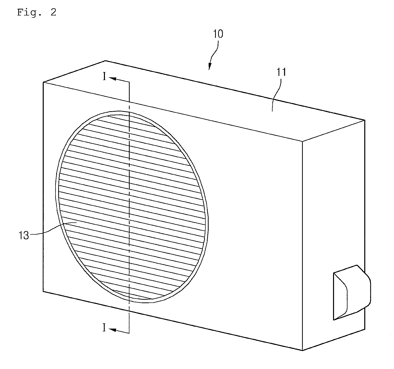
[0031]FIG. 3 shows a louver structure according to the disclosure, as a cross-sectional view taken along line I-I of FIG. 2.

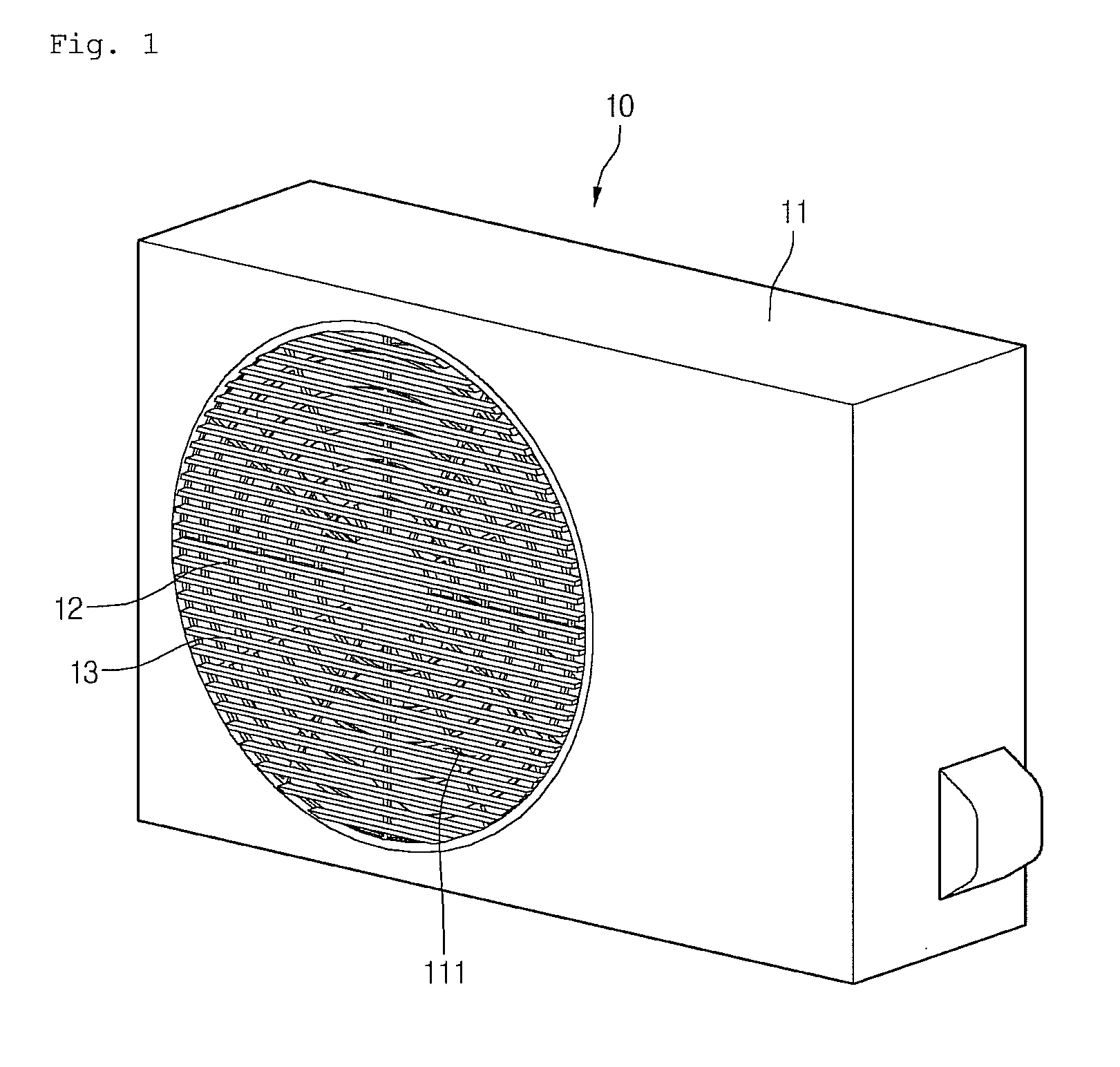
[0032]In FIG. 3, the plurality of louvers 13 can be placed horizontally or vertically. In addition, the louvers 13 close perfectly the discharge port 111 under condition parallel to the front of the case 11.

[0033]In detail, both ends of each of the plurality of louvers 13 are rotatably connected to the edge of the discharge port 111. First, it is described that the plurality of louvers 13 are placed in the horizontal direction and arranged adjacently to each other in the vertical direction.

[0034]When the plurality of louvers 13 are placed in the horizontal direction, a rotation axis may be protruded from both side ends of each louver 13. In addition, the rotation axis may be formed in the top end of the side end of the louvers 13. According to such a structure, when the fan 14 is driven and the suctioned outdoor air is discharged to the discharge port 111, the ...

second embodiment

[0038]FIG. 4 shows schematically a louver driving mechanism according to the disclosure, FIG. 5 shows a portion of the rear of the outdoor unit case equipped with the louver driving mechanism and FIG. 6 shows schematically a form in which the louvers are connected to the louver driving mechanism.

[0039]In FIG. 4 to FIG. 6, A connection bar 22 is extended to one or both ends of the louvers 13 and a pinions 21 is mounted in the end of the connection bar 22. In addition, a racks 20 may be arranged in the front or rear of the pinions 21. Further, the pinions 21 may be gear-coupled with the racks 20. The racks 20 is formed with lengths that may be gear-coupled with both of the pinions 21 connected to uppermost louvers 13 and the pinions 21 connected to lowermost louvers 13. Further, the racks 20 may be mounted inside the case 11 to enable reciprocal movement along the length of the racks 20.

[0040]Further, a driving motor M may be connected to any one of the pinions 21 connected to the lou...

third embodiment

[0045]FIG. 7 is a front view of the outdoor unit showing schematically the louver driving mechanism according to the disclosure, FIG. 8 is a cross-sectional view showing a process in which the louvers close the discharge port of the outdoor unit, as a cross section view taken along line II-II of FIG. 7 and FIG. 9 is a cross-sectional view showing a condition when the louvers close perfectly the discharge port of the outdoor unit.

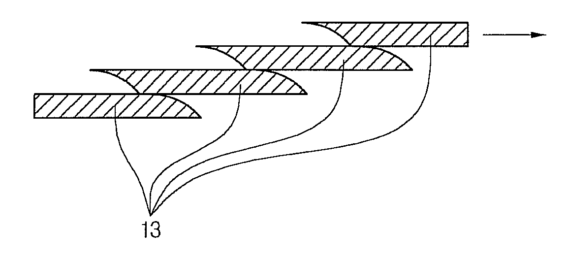
[0046]Referring to FIG. 7 to FIG. 9, the discharge port 111 of the outdoor unit 10 according to the disclosure may be selectively closed by the plurality of louvers 13 extending in all directions. The plurality of louvers 13 may be arranged to be overlapped with each other. In other word, a portion of one louver may be arranged to be vertically overlapped with a portion of another louver (refer to FIG. 8).

[0047]Specifically, the driving motor may be mounted in the center of the discharge grille 12 and the louver assembly having a fan type may be mounted in t...


PUM


Abstract

An outdoor unit for an air conditioner according to an exemplary embodiment of the disclosure, comprising: a case forming shape and having a suction port suctioning outside air and a discharge port discharging the suctioned air; a heat exchanger accommodated inside the case; a fan that is accommodated inside the case and forcibly circulate air; and a louver assembly revolvably mounted in the case so as to selectively open and close the discharge port.

Description

CROSS REFERENCE TO RELATED APPLICATION[0001]The present application claims priority under 35 U.S.C. 119 and 35 U.S.C. 365 to Korean Patent Application No. 2010-0086825 (filed on Sep. 6, 2010), which is hereby incorporated by reference in its entirety.BACKGROUND OF THE INVENTION[0002]1. Technical Field[0003]The present disclosure relates to an outdoor unit for an air conditioner.[0004]2. Description of the Related Art[0005]Generally, the air conditioner is an apparatus for cooling or heating air based on a refrigeration cycle including a compressor, a condenser, an evaporator and an expansion member.[0006]One of the condenser and the evaporator that is placed outdoors is heat-exchanged with outside air and the heat exchanger placed outdoors is called an outdoor unit.[0007]The heat exchanger situated inside the outdoor unit and an outdoor fan suctioning outdoor air to the inside of the outdoor unit and discharging to the outside of the outdoor unit are mounted.[0008]For a general outd...

Claims


Application Information

Patent Timeline
Patent Type & Authority Patents(United States)
IPC IPC(8): F25D17/04E06B3/94F24F1/48F24F13/12F24F13/14
CPCF24F1/48F24F13/12F24F13/1413F24F13/1486
Inventor JUNG, MIJINMOON, DONGSOOHA, SAMCHUL
Owner LG ELECTRONICS INC
Why Eureka
Try Eureka