Ribbon microphone and unidirectional converter therefor

a microphone and ribbon technology, applied in the field of ribbon microphones, can solve the problems of small ribbon diaphragm, low mechanical impedance of the ribbon diaphragm used for the ribbon microphone, and the use of an acoustic tube to increase the size of the entire ribbon microphon

Inactive Publication Date: 2015-05-05
AUDIO-TECHNICA
View PDF2 Cites 4 Cited by
  • Summary
  • Abstract
  • Description
  • Claims
  • Application Information

AI Technical Summary

Benefits of technology

[0027]A variable pressure in the acoustic box is caused by sound waves guided to the rear acoustic terminal of the ribbon microphone unit, and is canceled by the detective microphone, the speaker, and the drive unit. This operation is equivalent to that of the acoustic tube mounted on the rear acoustic terminal of the ribbon microphone unit. According to an aspect of the present invention, the ribbon microphone can have an omnidirectional component without an acoustic tube. The omnidirectional component can be combined with the original bidirectional component of the ribbon microphone to provide unidirectivity. A small high-sensitivity unidirectional ribbon microphone can be achieved since the unidirectivity can be provided without an acoustic tube.

Problems solved by technology

A ribbon diaphragm used for a ribbon microphone however has low mechanical impedance due to its small mass in comparison with a diaphragm of a dynamic microphone.
Use of an acoustic tube however increases the size of the entire ribbon microphone.
A decrease in size leads to a small ribbon diaphragm, which cannot provide high sensitivity.

Method used


Image

  • Ribbon microphone and unidirectional converter therefor
  • Ribbon microphone and unidirectional converter therefor
  • Ribbon microphone and unidirectional converter therefor

Examples


embodiment

Ribbon Microphone

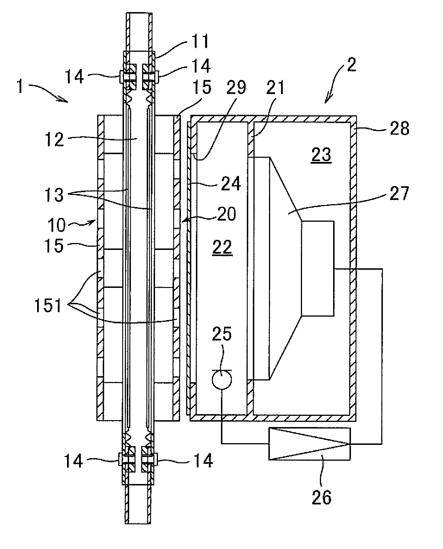
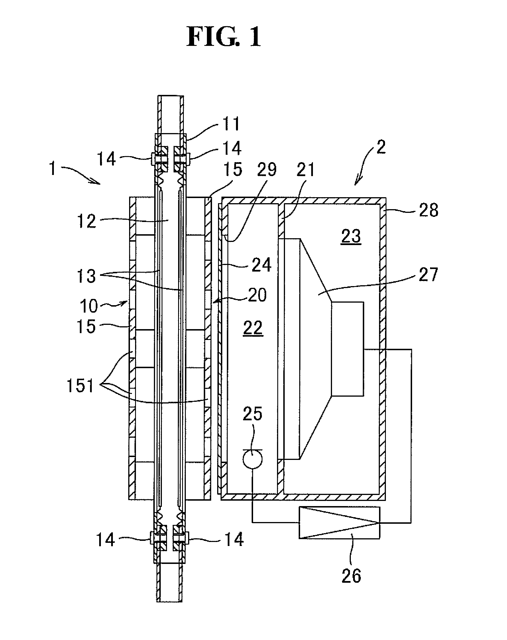
[0036]FIG. 1 illustrates a ribbon microphone according to an embodiment of the present invention. The embodiment involves a combination of the unidirectional converter according to an embodiment of the present invention and a ribbon microphone unit. In FIG. 1, a reference numeral 1 represents the ribbon microphone unit. As illustrated also in FIG. 3, a ribbon microphone unit 1 includes a frame 11, magnets 12, ribbon diaphragms 13, output terminals 14, and protective plates 15.

[0037]The frame 11 composed of a magnetic material has a rectangular shape (invisible in the drawing). The paired rod magnets 12 having rectangular cross sections are fixed on the respective facing longitudinal inner surfaces of the frame 11. The paired magnets 12 are magnetized in the same width direction and generate a uniform magnetic field between the paired magnets 12. The ribbon diaphragm 13 intersects the magnetic field.

[0038]The paired ribbon diaphragms 13 are disposed on the front and ...


PUM


Abstract

A ribbon microphone includes a ribbon microphone unit; an acoustic box for mounting a rear acoustic terminal of the ribbon microphone unit; a detective microphone mounted in the acoustic box, the detective microphone detecting sound waves identical to sound waves guided to the rear acoustic terminal of the ribbon microphone unit; a speaker comprising a diaphragm, the speaker being assembled in the acoustic box and varying the pressure in the acoustic box in response to the driven diaphragm; and a drive unit for driving the speaker so as to cancel a variation in pressure in the acoustic box in response to signals detected by the detective microphone, the variation being caused by sound waves guided to the rear acoustic terminal. This configuration extracts an omnidirectional component without an acoustic tube to achieve a small high-sensitivity unidirectional ribbon microphone and a unidirectional converter for the ribbon microphone.

Description

TECHNICAL FIELD[0001]The present invention relates to a ribbon microphone designed for providing unidirectivity and a unidirectional converter therefor.BACKGROUND ART[0002]A ribbon microphone includes main components, i.e., magnets generating a magnetic field and a ribbon diaphragm vibrating in the magnetic field in response to sound waves. The magnets are disposed on both sides of the ribbon diaphragm in the width direction and generates a magnetic field between the magnets on both sides. The magnets are supported by a frame composed of a magnetic material. The ribbon diaphragm with appropriate tension has both ends in the length direction fixed to the frame. The ribbon diaphragm vibrates in the magnetic field in response to sound waves to generate electrical signals in synchronization with the sound waves. Ribbon diaphragms are generally composed of an aluminum foil having high conductivity and low specific gravity. Ribbon microphones are disclosed in, for example, Japanese Unexam...

Claims


Application Information

Patent Timeline
Patent Type & Authority Patents(United States)
IPC IPC(8): H04R25/00H04R17/02H04R1/08
CPCH04R1/08H04R1/326H04R9/08H04R2410/05
Inventor AKINO, HIROSHI
Owner AUDIO-TECHNICA
Why Eureka
Try Eureka