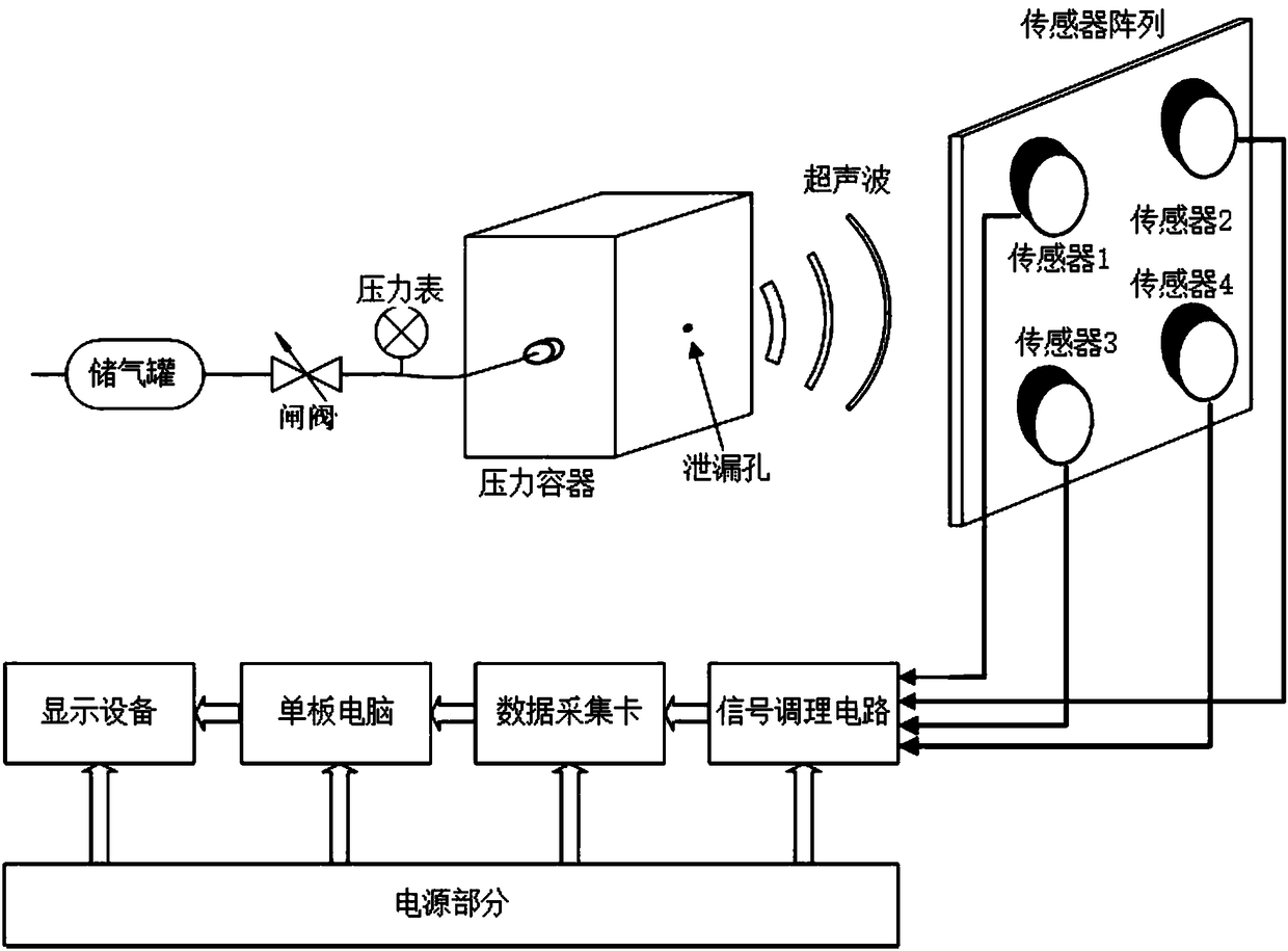
Surface array ultrasonic gas leakage point positioning detecting device and method
A detection device, gas leakage technology, applied in the measurement device, by detecting the appearance of fluid at the leakage point, testing the fluid tightness, etc., can solve the problems of high requirements for measurement conditions, inability to calculate the leakage point, poor real-time performance, etc., to achieve Widen the scope of application, overcome the inability to accurately locate, and improve the effect of accuracy
Active Publication Date: 2018-08-24
BEIJING INSTITUTE OF TECHNOLOGYGY
View PDF8 Cites 12 Cited by
- Summary
- Abstract
- Description
- Claims
- Application Information
AI Technical Summary
Problems solved by technology
[0004] In order to solve the problems of low precision, poor real-time performance, high requirements for measurement conditions, and inability to calculate the three-dimensional coordinates of the leak point in the existing gas leak detection technology, an area array type ultrasonic gas leak point location detection device and method are provided. The leakage point existing in the space can be located, and any shape of the measured container or pipeline can be detected, which greatly broadens the scope of application of the ultrasonic leak detection and positioning system
Method used
View moreImage
Smart ImageViewing Examples
Examples
Embodiment 1
[0032] This embodiment discloses an area-array type ultrasonic gas leakage point location detection device and method, and the specific implementation steps are as follows:
Login to View More PUM
 Abstract
The invention relates to a surface array ultrasonic gas leakage point positioning detecting device and method, and belongs to the technical field of gas leakage detection. The object of the present invention is to solve the low accuracy, poor real-time performance, high requirements for measurement conditions, and incapability of calculating the three-dimensional coordinates of a leakage point ofthe gas leak detection technology in the prior art, and to provide a surface array ultrasonic gas leakage point positioning detecting device and method. The detecting device comprises a centrally symmetric multi-element ultrasonic plane array and an ultrasonic signal acquisition and calculation device. A software part includes a system basic processing module and a leakage positioning module. Thebasic processing module realizes interference signal elimination, abnormal data removal and data point increase by digital filtering, waveform selection and cubic spline interpolation. The leakage positioning module calculates the arrival time difference, a sound pressure amplitude ratio, and a data fusion and spherical coordinate equation to calculate the spatial location of a leakage point.
Description
technical field [0001] The invention relates to an area-array ultrasonic gas leakage point location detection device and method, belonging to the technical field of gas leakage detection. Background technique [0002] Recently, my country's economy continues to develop rapidly, the scale of industrial production continues to expand, the use of pressure vessels is becoming more and more popular, and the number is also increasing. Problems caused by leaks in pressure vessels are also increasing. In today's situation of constantly focusing on environmental protection and energy saving, it is necessary to continuously improve the safety and reliability of pressure vessel pipelines, which puts forward higher requirements for leak detection technology. In leak detection in many industries, it is not only required to judge whether there is leakage in the tested appliance and calculate the leakage amount, but also to give the location of the leak point to facilitate the maintenance...
Claims
Login to View More Application Information
Patent Timeline
 IPC IPC(8): G01M3/24
CPCG01M3/24G01M3/243
Inventor 王涛王小然徐孟杰
Owner BEIJING INSTITUTE OF TECHNOLOGYGY
Features
- R&D
- Intellectual Property
- Life Sciences
- Materials
- Tech Scout
- Unparalleled Data Quality
- Higher Quality Content
- 60% Fewer Hallucinations
Learn More Browse by: Latest US Patents, China's latest patents, Technical Efficacy Thesaurus, Application Domain, Technology Topic, Popular Technical Reports.
© 2025 PatSnap. All rights reserved.Legal|Privacy policy|Modern Slavery Act Transparency Statement|Sitemap|About US| Contact US: help@patsnap.com


