
Defibrillator location tracking device

a technology of location tracking and defibrillator, which is applied in the field of external defibrillators, can solve the problems of reducing the amount of blood pumped to the various parts of the body, irregular heart beating, and not at all,

Active Publication Date: 2015-05-05
PHYSIO CONTROL INC
View PDF32 Cites 24 Cited by
  • Summary
  • Abstract
  • Description
  • Claims
  • Application Information

AI Technical Summary

Benefits of technology

The system enhances the efficiency of defibrillator management by providing real-time location tracking and movement monitoring, facilitating quicker access and reducing the likelihood of delayed administration, thus improving survival rates in emergency situations.

Problems solved by technology

Sometimes, however, the electrical control system of the heart malfunctions, which can cause the heart to beat irregularly, or not at all.
Some types of arrhythmia may result in inadequate blood flow, thus reducing the amount of blood pumped to the various parts of the body.
In an SCA, the heart fails to pump blood effectively, and, if not corrected, can result in death.
It is estimated that SCA results in more than 250,000 deaths per year in the United States alone.
When that happens, the heart does not pump enough blood to deliver enough oxygen to the vital organs.
The person's condition will deteriorate rapidly and, if not corrected in time, will result in death, e.g. within ten minutes.
A challenge with defibrillation is that the electrical shock must be administered very soon after the onset of VF.
Regardless, VF can occur unpredictably, even to a person who is not considered at risk.

Method used


Image

  • Defibrillator location tracking device
  • Defibrillator location tracking device
  • Defibrillator location tracking device

Examples


Embodiment Construction

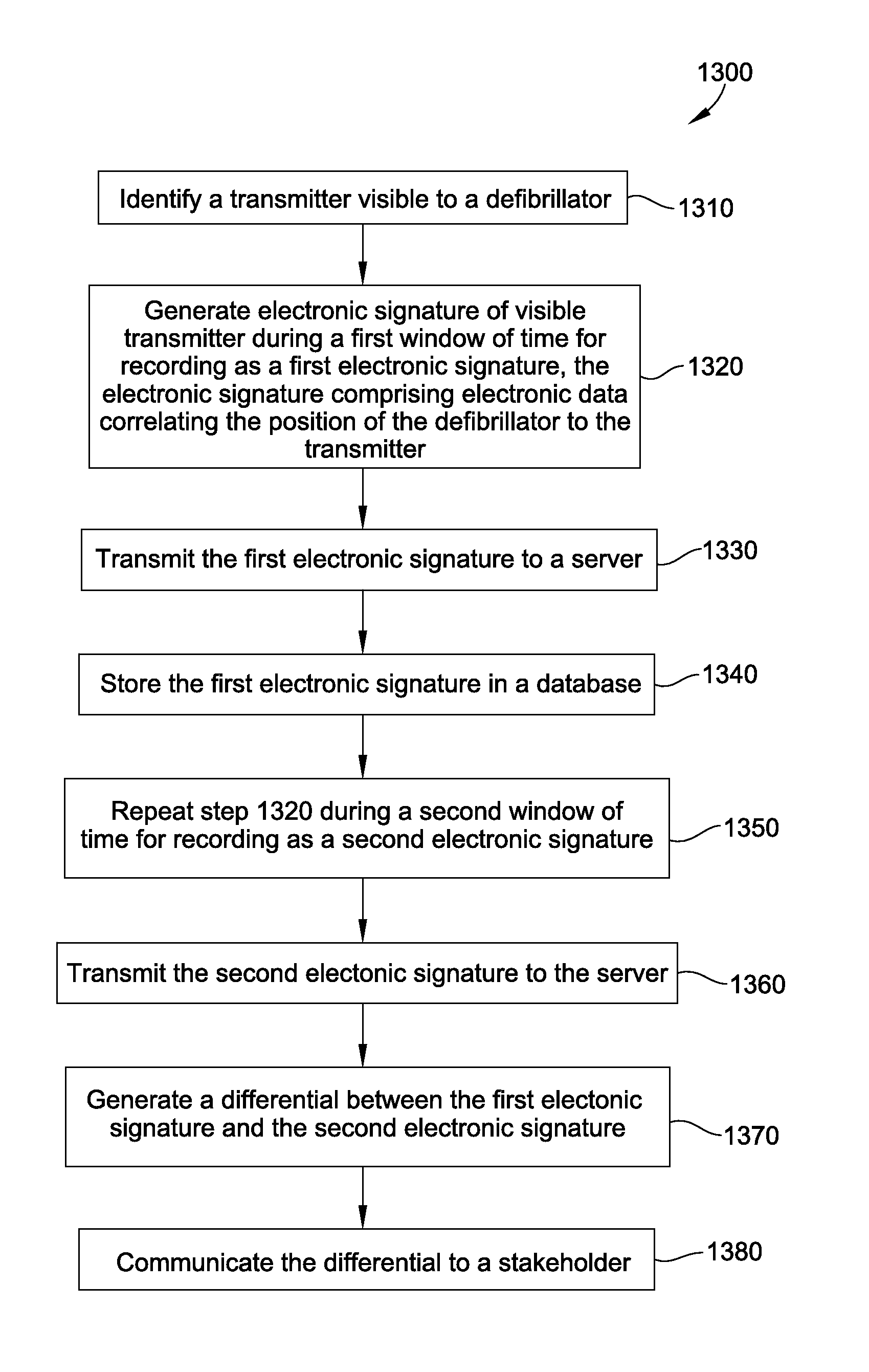
[0037]Broadly speaking, a defibrillator is disclosed for communication with a transmitter associated with a location. The defibrillator is configured to generate an electronic signature for determining a position of the defibrillator within the location. The electronic signature includes electronic data correlating the position of the defibrillator to the transmitter. The defibrillator is configured to generate the electronic signature during a first and a second window of time to define a first and a second electronic signature. A differential between the first and the second electronic signatures corresponds to a positional state of the defibrillator, indicating movement within or between two locations. The electronic data correlating the position of the defibrillator to the transmitter may include GPS data. In a disclosed system, the first electronic signature is stored in a database and a server is configured to generate the differential and to communicate the positional state o...


PUM


Abstract

A defibrillator is disclosed for communication with a transmitter associated with a location. The defibrillator is configured to generate an electronic signature for determining a position of the defibrillator within the location. The electronic signature includes electronic data correlating the position of the defibrillator to the transmitter. The electronic data may include GPS data. The defibrillator is configured to generate the electronic signature during a first and a second window of time to define a first and a second electronic signature. A differential between the first and the second electronic signatures corresponds to a positional state of the defibrillator, indicating movement within or between two locations. In a disclosed system, the first electronic signature is stored in a database and a server is configured to generate the differential and to communicate the positional state of the defibrillator to a stakeholder. Methods of use are also disclosed.

Description

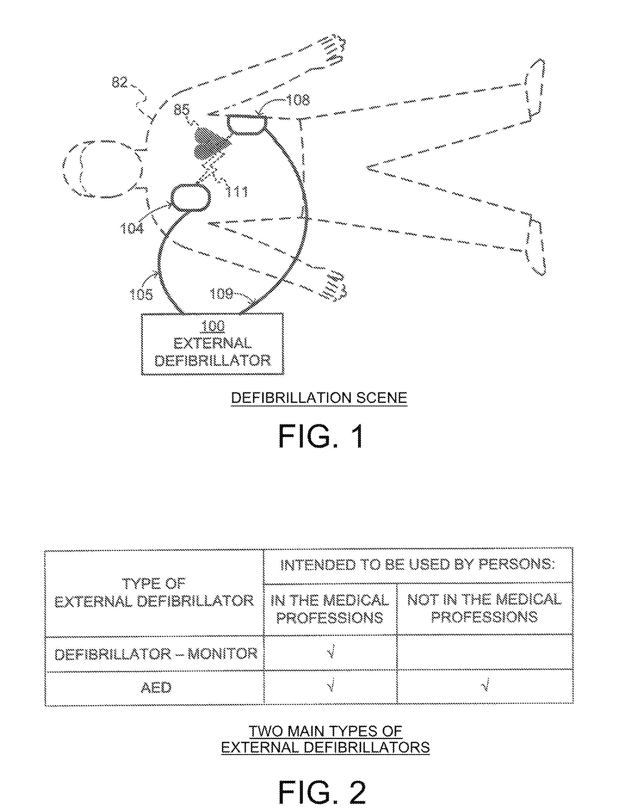
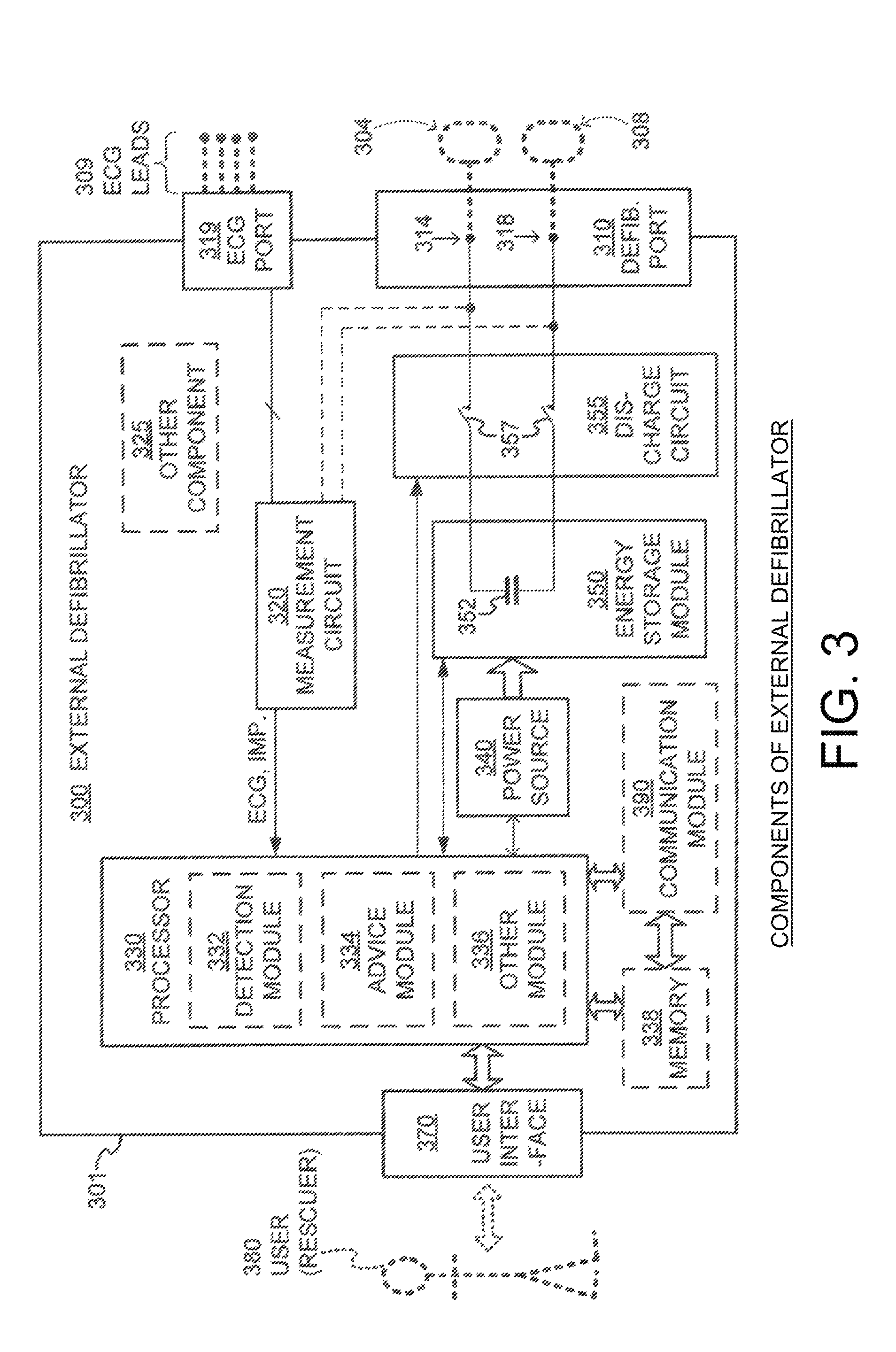
FIELD[0001]This invention generally relates to external defibrillators.BACKGROUND[0002]In humans, the heart beats to sustain life. In normal operation, it pumps blood through the various parts of the body. More particularly, the various chamber of the heart contract and expand in a periodic and coordinated fashion, which causes the blood to be pumped regularly. More specifically, the right atrium sends deoxygenated blood into the right ventricle. The right ventricle pumps the blood to the lungs, where it becomes oxygenated, and from where it returns to the left atrium. The left atrium pumps the oxygenated blood to the left ventricle. The left ventricle, then, expels the blood, forcing it to circulate to the various parts of the body and from where it returns to the right atrium to start the oxygenation-deoxygenation cycle of the blood all over again.[0003]The heart chambers pump because of the heart's electrical control system. More particularly, the sinoatrial (SA) node generates a...

Claims


Application Information

Patent Timeline
Patent Type & Authority Patents(United States)
IPC IPC(8): H04W4/04G01S5/02G01S19/17G06F19/00H04L29/08H04W4/029
CPCG01S19/17G01S5/0226H04W4/043G06F19/3418H04W4/04H04L67/12G16H40/67H04W4/029
Inventor GALVIN, MOIRA MONTGOMERYDREW, KEVIN CKLUMP, TODDKNAPINSKI, JOHN ROBERTLEWIS, DANA SSILKES, STEVE M
Owner PHYSIO CONTROL INC
Learn More